The following lists the history of important new features and bug fixes in the PSCAD V5 product line. Links are provided for easy access to the relevant topics where possible.
For a history of changes to the PSCAD X4 product line (v4.3 to v4.6), click here.
Version v5.0.0 is the initial major release of the PSCAD V5 product line. This release represents the greatest change to a single release, in terms of new features and functionalities, than any previous PSCAD version.
Release v5.1.0 is the first minor upgrade to the original V5. This release includes both new features and bug fixes.
Disabled Module Parameters: The ability to add parameters to page modules was introduced way back in PSCAD v4.3.0 (circa 2010), along with the ability to disable these parameters.
Just prior to the release of PSCAD v5.0.0 in 2021, we identified the seriousness of disabling module parameters, as they are connected directly as inputs to actual circuits, drawn within the module schematic. If a disabled parameter is connected to an import tag on the schematic, which is likely an input to a controller or similar, what value should be passed into the import tag? The answer is important, as it can affect the accuracy simulation results.
Our initial solution in v5.0.0 was to generate an error message when a disabled module parameter was encountered. We quickly discovered following the release that some users were using the disabled module parameter feature to organise their parameters visually, and as such were inundated with error messages on compile of their projects. We provided a quick solution to this by simply changing theses messages to warnings in v5.0.1 and onward. However, this was not a good solution and just masked the issue, so we came up with a better solution for v5.1.0.
When a project is imported into PSCAD v5.1.0, it is scanned for disabled module parameters. If encountered, the above dialog is presented on a per project basis. Please take care in selecting one of the three options provided. If you need to go back and change the settings after import, it may be done on a per module basis, via the canvas settings:

Intel® Visual Fortran Compiler: Version 12.0 is no longer supported. Support has been added for OneAPI for Windows 2024, 2025.
GFortran Compiler: Version 4.6.2 is no longer supported. Support has been added for version GFortran 13.2.
Operating Systems: The Windows 7 OS is no longer supported. Support has been added for Windows 11 (64-bit only).
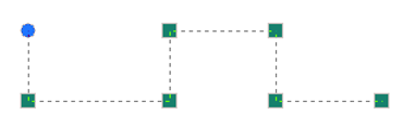
Automatic Page Module Creation from a Selection: Users may now collapse any selection of schematic components directly into a page module. Simply select one or more components, using any of the available selection methods, right-click and select Generate | Module. The algorithm will consider both hard-wired and wireless signals that cross the selection boundary. Wireless signals include both those from data and node labels from/to output/input parameters, as well as #OUTPUT directive signals, generated within components, that are passed out via text parameters. If necessary, new parameters will be added to the generated module component to accommodate any wireless signals. All in all, the module component should be run ready once generated.

New Subsystems Definition Script Segment: A new script segment entitled Subsystems, is now available for use in all, non-module component definitions. New script directives (#SUBSYSTEM, #ENDSUBSYSTEM, #PORT, #TLINE, and #ENDTLINE) allow users to define two or more subsystems and declare which components ports belong to which subsystem. A section encompassed by the #TLINE/ENDTLINE directives, houses the contents of the solved *.tlo/*.clo file (generated by the PSCAD Line Constants Program), along with specifications for port connections.

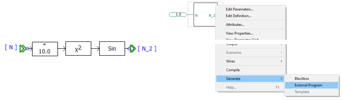
C-Coder: PSCAD may now be used to generate a fully formed, ANSI-standard, C language program, which may be run independently of EMTDC. The resulting code can then be used to program micro-controllers, etc.
C-language program generation is accomplished by constructing a control circuit using a collection of our more basic, master library components, specifically from the Control System Modelling Functions (CSMF) section. Once constructed inside of an encapsulating page module, the C-language program is generated with a single click.
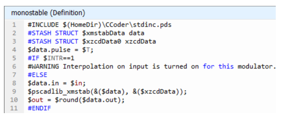
To facilitate this functionality, we have added a brand-new component definition script segment, called ‘C’, where we have placed C-code script that is functionally equivalent to the component’s original Fortran-based script. The ‘C’ component script segment is only ever considered when generating a C-language program.

|
 |
|
Fortran Segment |
C Segment |
Previous Run Playback: Previous Run Playback enables a replay of a previously run simulation, where the output results have been written in *.psout format (i.e. Save Channels to Disk? Is set to Advanced (*.psout)).

Once the simulation is complete, simply add the resulting *.psout file as a Previous Run project resource:

Once added, right-click again and select Play and then the run stored within the *.psout file you would like to play back:

The playback speed is adjustable. The graphs, controls, instruments, and animations will be re-displayed during the playback. The ribbon control bar will automatically display a Playback tab, which provides an assortment of controls:

Previous Run Playback is useful for doing presentations where performing the simulation may take a long time or perhaps the simulation is too fast for in-simulation analysis.
Component Library Viewing Pane: A new viewing pane has been added that provides a searchable environment for finding and viewing available component models, across the entire workspace.

Filters provide the ability to focus the view on a specific project, or across all loaded projects in the workspace. Fully searchable, users can quickly find what they are looking for and add an instance of the component to the schematic with a single click. A viewing window at the bottom of the pane provides information about the component, including its graphical appearance.
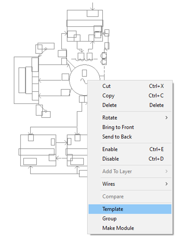
Component Templates: Pre-configured collections of components and modules may now be consolidated and stored as a Template object. Functional in both library (*.pslx) and case (*.pscx) projects, simply select a group of components on the schematic canvas, right-click and select Generate | Template.
Once templated, the pre-configured group of components are stored in the project under the Templates branch in the workspace tree:
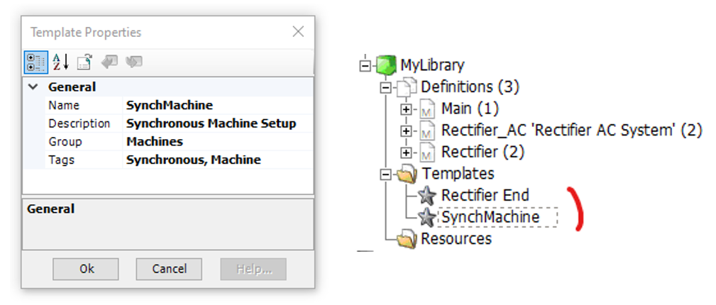
Once created, the template becomes viewable and searchable (according to its name and given Tags) via the Component Library Viewing pane. An instance of the template can be created either from the Component Library Viewing pane, or directly from the workspace tree.
Allowing EMTDC to Run Ahead of PSCAD (Live): Starting in PSCAD v5.1, EMTDC by default will run unfettered to PSCAD. That is, EMTDC is not obligated to wait for PSCAD to process data it sends back for plotting, etc., before proceeding to the next time step. This increases the simulation speed, and along with other speed optimisations, helps EMTDC to run faster than it ever has before, especially for very parallel simulations.
The only instance where perhaps EMTDC running ahead would not be desired is when there is a necessity to manually modify online controls, such as sliders and switches, where it is important for PSCAD to be in synch with EMTDC, so that the manual control signal variations occur at the proper time. As such, a means to disable EMTDC running ahead is provided in PSCAD via a ribbon button called Live.

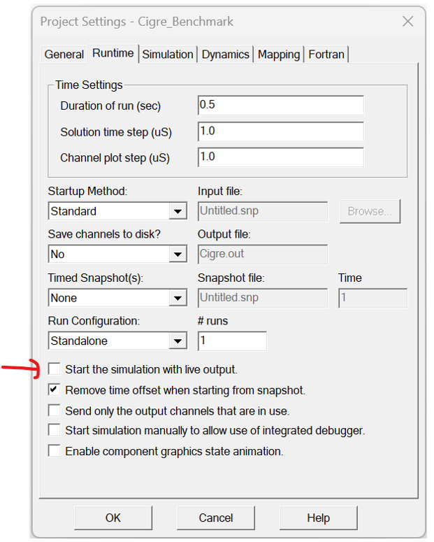
Note that the Live setting is also a project setting, that can be saved as always on:
Added Niceties to Enhance the Circuit Building Experience: We have added several new features that will help to make user’s circuit-building experience more enjoyable:
Automatic Output Channel Creation: A component context menu option has been added that will scan the component for output parameter signals, and the automatically construct an output channel with a data label attached, with names pre-set to the output parameter name. In addition, users may take this one step further by automatically creating and adding these output channels to a graph, or a meter in a control panel.

Add Module Interface: A new schematic canvas menu function allows you to quickly add XNodes or import/export tag components to a module canvas, based on any module port or parameter that has not already been paired with one of these components. The component is added pre-named to match the chosen parameter or port name.

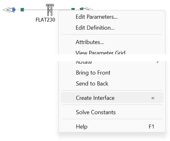
Auto T-Line/Cable Interface: A new transmission line/cable context menu function allows you to quickly generate a pre-configured, interface component to correspond with any transmission segment properties component. Simply right-click on the transmission segment properties component and select Create Interface.
Component Wire Insertion: A new mechanism has been added to allow users to automatically insert a component inline within a wire, without going through the cumbersome steps of breaking the wire apart. Simply move the component atop a wire, lining up the connection ports, hold down the space bar and release the mouse button. Voilà!
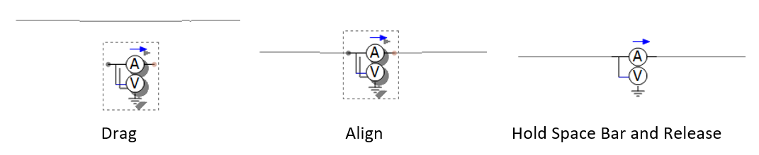
Or simply align the component atop the wire, right-click and select Wires | Insert Selection into Pathways.

This functionality not only helps when adding series components like ammeters or multimeters but also helps simplify automated construction of circuits using Python script.
New Group Box Display Tool Added: A new group box display object has been added. Like a sticky note, this object is optimised for use as a visual grouping tool. The group box can be adjusted for a variety of border styles and colours, as well as a coloured or transparent background.

Customizable Default Settings for Various Objects: Users can now adjust the default properties for most newly created schematic objects. For example, if you prefer the drawing grid to be enabled when adding a new graph, you can set the property default as enabled. Object default properties are part of the Application Options dialog, and so these settings are stored in your user profile and will persist across multiple workspaces.

Component Definition Enhancements: Some new enhancements have been made to component definitions:
Tag Setting: Users can add tag names to their custom component definitions to help with searching; for both the main search tool, and when using the Component Library Viewing pane.

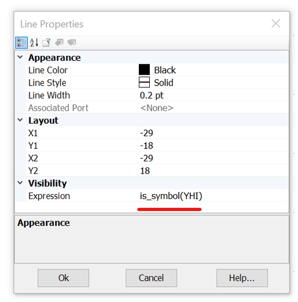
New Evaluation Functions for Conditional Statements: Three new evaluation functions have been added for use in component definition graphic and parameter conditional statements, which may be used to control the enable/disable/visible state of parameters or graphics.
is_symbol(<symbol_name>): This function will return true if a valid signal name (such as ABC123) is entered as a value in the parameter corresponding to the entered symbol name. Otherwise, a false is returned.
is_literal(<symbol_name>): This function will return true if a valid literal (such as 1.23) is entered as a value in the parameter corresponding to the entered symbol name. Otherwise, a false is returned.
is_empty(<symbol_name>): This function will return true if nothing is entered as a value in the parameter corresponding to the entered symbol name. Otherwise, a false is returned.
New Resource Macros for Automating File Names and Paths: A huge number of new macros have been added to help with the automation of resource file names and paths (this includes file and paths used in project settings and application options.
For example:
$(FileVersion): Substitutes the last version of PSCAD used to save the current state of the project file (ex. 4.6.3).
$(Creator): Substitutes the name of the project creator (the user who initially created the project).
$(CreateDate): Substitutes the date the project was created.
$(CreateTime): Substitutes the time the project was created.
Plus, many more.
For a complete list of new macros, see Complete Macro List.
Miscellaneous Niceties: In addition to the above, the following new features have been added:
Drag Panning: Users may now drag objects, such as a graph panel or component, to the edges of the viewable canvas and PSCAD will pan (i.e., auto-scroll) in the direction the mouse is pulled.
Selectable IP Address: PSCAD now provides all IP addresses available on the host machine in the Application Options (under Workspace | Simulations), so user can manually select which one to use. This can help resolve any IP address contention issues that arise.
Project-Based Fortran Compiler Settings: Fortran compiler settings may now be specified on a per-project basis as needed (as opposed to purely application-based in previous versions). By default, PSCAD will use the compiler settings specified in the Application Options | Dependencies category. However, if different compiler settings are necessary for different projects within the same workspace (for example, a PNI simulation launching multiple projects in parallel), users may now override the compiler settings set in the Application Options, on a per-project basis via a Project Settings selection.

The ability to set Fortran compiler and Visual Studio configurations on a per-project basis is also now available to be overridden on a per simulation task basis. This enables you to run simulations sets in sequence that include simulation tasks using different compiler/Visual Studio combinations in different simulation sets.

Compiler Advanced Options: The project settings now include far greater access to internal compiler settings, via an Advanced Options button, within the Compiler Options area, under the Fortran tab.

Project-Based, Command Line Event Options: Users may now launch command line-based programs or events at specific times between building and running their simulation. Launch events can be specified to occur during pre-build, post-build, pre-run, and post-run, via the Build Events category in the Compiler Options dialog (see Compiler Advanced Options above).
An example usage for this feature is say a user needs to run a certificate program after generating the EMTDC executable file, before it runs, to allow their local security program to run first. In this instance, the user would provide command line commands in the post-build or pre-run input fields.

Project-Based, Multiple MATLAB Version Support: Users may now associate different versions of MATLAB with different case projects. This functionality is controlled from within the Compiler Advanced Options as shown above. By default, the MATLAB version specified in the Application Options is used, but this may now be overridden at the project level.
SCons Replaces Legacy Make/NMake Build System: The legacy make/nmake command-line interface tool, which has been used by PSCAD since its inception to provide build instructions for the associated Fortran compiler (via the generation of a configuration file called a makefile), has been replaced with the more modern, Python-based tool called SCons (https://scons.org/).
SCons is an open-source, software construction tool. Think of SCons as an improved, cross-platform substitute for the classic make utility with integrated functionality, like autoconf/automake and compiler caches such as ccache. In short, SCons is an easier, more reliable way to build software.
SCons makes the dependency management and building of large simulations much faster and more reliable.

Simulation Speed Enhancements (PSCAD Side): As user’s projects become larger and require more computing resources, we have been working hard to identify choke points and other processing inefficiencies.
PSCAD requires different resource levels allocated, depending on how it is being used. If PSCAD is running on the same computer, on which the EMTDC simulations are running, then it is a good idea to limit the number of threads that PSCAD is allowed to run. If the simulation (EMTDC) is being launched on a different computer, then PSCAD should be free to use all the resources on its computer to process the data coming back from the simulations.
A new application option is added to allow the user to limit (or not limit) the number of threads PSCAD can run on its computer. By default, this is set to ¼ of the machine’s cores, but it is adjustable by the user.

Transmission Lines in Blackbox: Overhead transmission lines and underground cables are now supported when blackboxing modules. Utilizing a brand-new definition script segment called Subsystems, users may include transmission systems within a module to be blackboxed, provided both ends of each line exist within the same module. The presence of transmission lines also means that multiple, electrical subsystems are now supported for the first time, within non-module components.

Other Blackbox Enhancements: The following describes various other enhancements that have been added to Blackbox:
Definition Description: Blackboxed component definition descriptions are now copied from their respective source module. A new blackbox application option is added to accommodate user entry of definition labels. These labels are appended to any existing labels.
Options: Blackbox-related application options are now presented as a pop-up dialog at each blackbox operation. The options presented each time are read from those set within Application Options | Blackbox category.
Co-Simulation Component: Any Co-Simulation component that may exist in the module being blackboxed, is now fully supported.
Subroutine Naming Convention: To avoid possible conflicting subroutine names, Blackbox now ensures that the subroutines it creates are unique from those created by PSCAD, for EMTDC. Blackbox now adds ‘BB’ to the subroutine names: BBDyn, BBDyn_Begin, BBOut and BBOut_Begin.
Combined PMR/PNI Simulations Now Possible: Those who utilise the High-Performance Computing (HPC) functionalities in PSCAD, rejoice! It is now possible to simultaneously run a Parallel Multiple Run (PMR) of a Parallel Network Interface (PNI) simulation. Setup of such a simulation is straightforward: Simply provide Task Count and Maximum Volley parameters to the Simulation Set encapsulating the PNI simulation:
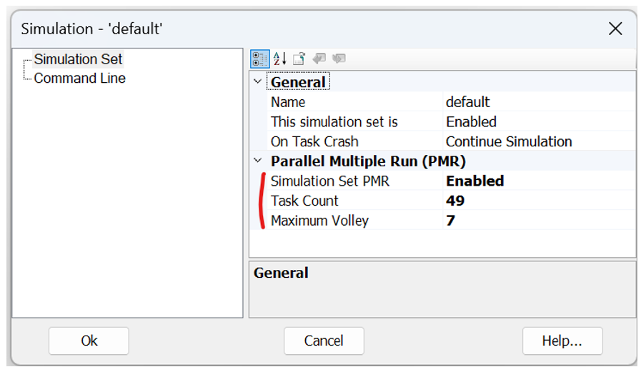
Note that usage of the Rank Number tag in your PNI simulation projects is still necessary as per a standard PMR simulation.
![]()
Single Dialog when Launching a Simulation Set Containing Manually Started Projects: When launching a simulation set containing two or more projects that are set to manually start with an integrated debugger, PSCAD will now issue a single dialog to allow selection on whether to manually start or not, for all projects in the simulation set.

In previous versions, individual dialogs would pop-up for every project set to manually start. If users so desire, there is a custom button on the above dialog that provides the ability to set project launch configurations on an individual basis.
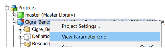
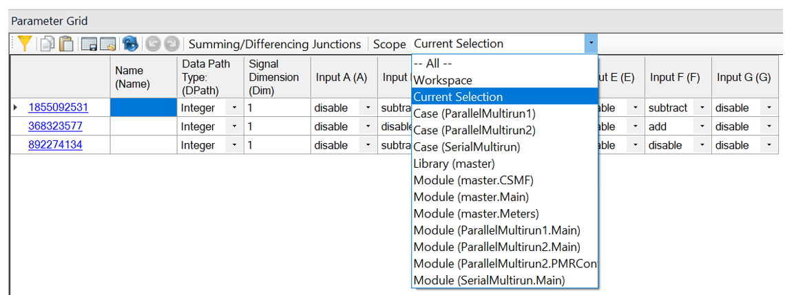
The Parameter Grid Goes Workspace Wide: The parameter grid feature is now even more powerful. In addition to the ability to filter results by component parameter category page, it now boasts a selectable Scope drop list, which can limit results by project type (i.e., case or library), or by any module that exists in the workspace. Users may even set the scope of results across the entire workspace, to include results from all modules in all loaded projects.

Other Parameter Grid Enhancements: The following describes various other enhancements that have been added to the Parameter Grid:
Project Settings: Project settings dialog contents are now supported in the parameter grid.
Canvas Settings: Canvas settings dialog contents are now supported in the parameter grid (right-click on any schematic canvas).

Component Graphics Objects: Component definition graphic object properties are now supported in the parameter grid.

Viewing Only Selected Components: A new scope has been added so when viewing parameter grid results, you can focus only on selected components. View the parameter grid as normal, select which components you want to focus on and select the scope as Current Selection.
Wire Mode Refined: Wire mode has been refactored under the hood for better performance, stability, and ease of use.
Python Interpreter Upgrade: The embedded Python interpreter has been upgraded from Python 3.7 to Python 3.13.5, allowing embedded scripts access to new features of the language. These include a simpler syntax for dictionary union operations, the walrus operator (:=), debug-style f-strings (f"{expr=}"), and improved type-hint syntax to name a few.

Additional Python-Related Updates: The following functionalities have been added existing Python scripting capabilities.
Paste Definitions: Paste Definition & Paste Definitions w/ Dependents is now fully implemented. Previously the record function added these commands to the script, but they were added as comments (preceded by #), as they were not fully implemented.
Node and Branch Search: Users may now search for a specific node or a branch, given the node or branch number and the subsystem.
Update Python Library Button: A new button has been added to the Tools tab in the ribbon control bar, allowing users to update the mhi.pscad Python Automation Library as a per-user package.
Port Specification: Users can now create a configuration file, ~/.mhi.pscad.py, which can be used to specify a port or port range for Python automation to use.
Mirror/Rotate Restriction Control for Component Definition Graphic Objects: Component graphic objects may now have of their graphics orientation locked to prevent mirroring and to restrict rotating of those objects.
A new option is added to the component definition graphic object properties called Orientation Lock, which can be used to lock enable the locking.

Short-able XNodes: XNodes may now be shorted together (i.e., without a defined branch between them). This was an issue for users with module schematics resulting in shorted XNodes, based on compile-time scenarios. A preprocessing step is now added to identify shorted XNodes, which are then mapped to the same node following global node mapping.
Easy Kill of Launched Simulation Processes: If PSCAD crashes during a large simulation, or is unable to stop all running simulation processes, it can be difficult to track these down and kill them manually. A kill option has been added the to simulation set, which will find all simulation processes pertaining to that set by name and kill them. This will be done regardless of whether they were started by the current instance of PSCAD or not.

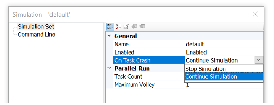
New Option to Automatically End Simulation Set on Task Crash: If a single EMTDC instance crashes or dies during a simulation set run, that simulation set will become stuck, continuously waiting for the dead task. This could put an exceedingly large amount of stress on a machine until the task is manually killed. No longer. We have added a simulation set option that will automatically shut down the entire set, if one or more tasks crash or die.
Conditional Statements in Flyby Script Segments: Conditional statements (#IF, #ELSE, #ENDIF, #CASE) are now allowed in the FlyBy component definition script segment. This allows users to change the flyby display over custom components, depending on user input. This is especially important when say connection ports vary in dimension and/or type.

Instrument Properties: All display instruments (i.e., PolyMeter, PhasorMeter and Oscilloscope) now possess their own unique properties that may be adjusted independently of their associated Output Channel. In previous versions, display limits were based on the minimum and maximum display limit parameters of the output channel linked to the device. Note that when an instrument is first created, their default property values are still derived by default from the associated output channel.

Instrument properties may be adjusted at any time: Prior, during, or post simulation.

Animated Data Labels: Data labels may now be set to display the value of their associated signal. Utilizing the Animated Graphics functionality in PSCAD, data label parameters may be adjusted to display the dynamic signal value during the run, or the maximum or minimum signal value that occurred over the entire run.
Simply ensure that you have enabled Animated Graphics in the project settings. Then, adjust the data label parameters to display what is needed.

Component Ports May Now Be Defined as Constant: Ports within component definitions may now be set as constant when the port is defined as non-electrical. If the port is operating as an input, it will only accept a constant signal. If functioning as an output, it will create a constant signal.
Master library components that generate constant signals, such as the constant tags, rank, Delta-T, etc., have already been modified in v5.1.

Application Options Import/Export to *.csv File: Users may now export or import their application options, to or from a Comma-Separated Values (*.csv) file. This comes in handy when the exact same application option settings need to be setup over multiple machines on the network. Simply export the options to a *.csv file on the first machine, and then import to all others.

Miscellaneous Addressed Deficiencies: In addition to the above, the following deficiencies have also been addressed:
Loaded Project Limit: The total number of projects per workspace has been increased to 1024.
Component Licensing Port Specification: A port number to be used by Component Licensing may now be directly specified in the Application Options. The default is set to any port.

Snapshot and Map File Names/Paths: PSCAD and EMTDC now support full, Windows 260-character file paths and names for snapshot (*.snp) and map (*.map) files. Previously these file names were limited to 34 characters maximum, and therefore could only be assumed to reside in the temporary folder (thereby avoiding long absolute paths). Also, PSCAD can now provide (and EMTDC accept) full snapshot and map file paths via the command prompt.
PNI and Foreign Transmission Segments: When compiling a PNI simulation that includes foreign transmission segments (i.e., the segment properties are located on another computer), the resulting LCP output files (*.tlo/*.clo) are now complied into the local folder on the computer being used to launch the simulation.

Paste Transfer (Local Only): A new paste transfer option has been added which, when selected, ensures that only definitions local to the project where the copy action occurred, are transferred to the destination project. That is, all definitions that are part of referenced library projects are not included in the paste transfer.

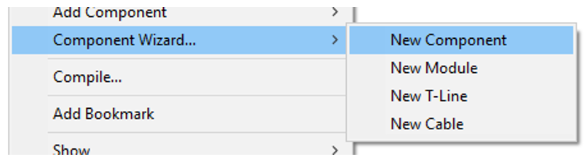
Component Wizard Quick Options: When accessing the component wizard from the schematic canvas, new menu items have been added for quick configuration of the wizard to specific component types.
Jumbo-Sized Canvas and PSCAD v4.6: PSCAD v5.1 now supports jumbo-sized canvases on Save As v4.6 format. Using a tile-sweep algorithm, PSCAD will split any Jumbo canvas it encounters into smaller canvases, while producing minimal changes to the structure of the schematic circuit. These smaller canvases are stored as module definitions in the project definition list and must be added connected within the project manually in PSCAD v4.6. For example, if a jumbo module canvas is named MyCanvas, the supplementary modules created will be called MyCanvas_1, MyCanvas_2, etc.
Workspace Save and Open Projects: When saving a workspace, PSCAD now additionally tracks and saves which projects were being viewed at the time of save. So, when the workspace is reloaded, only these projects (viewed during the last session) will be re-opened in the schematic canvas view. This is helpful in instances when a workspace contains many projects, but only a few are being focused upon.
*.inf/*.map File Updates: The *.inf file (and the output channel part of the *.map file) have been updated to include the full module hierarchy path to where the output channel is in the project. This extra information was not included at all in versions before v5.1.0.

Launch Mode: New, more sensible buttons have been added to the ribbon Tools tab, for the easy facilitation of Local (local machine) or Cluster Launch (multiple machines using the Cluster Launch System (CLS)) types of simulations.

Resources Branch Multi-Select: Users may now per perform actions (such as Remove) on multiple resources simultaneously.

Quick Search by Name: PSCAD now allows users to quickly search for other components that possess the same name (from the component Name parameter). This may be used to quickly search for t-line or cable ends, data labels, node labels, etc. The results of the search are provided in the Search Results pane, complete with navigable links.

Component-Based Virtual Wires: Regardless of whether or not Virtual Wires are enabled on a schematic canvas, users can now quickly display virtual wires specific to a single component. Simply right-click on a component and select Wires | Show Virtual Wires.

Undo/Redo in Component Definition Script Section: Full undo/redo support has been added to the component definition editor script section. Both Ctrl + z and Ctrl + y hotkeys are functional, plus new buttons were added to the Scripts ribbon tab.
Control Panel Creation via Drag and Drop: Control interfaces in control panels may now be dragged onto a blank part of the schematic canvas to create a new control panel (Ctrl + left-mouse drag).

Drag and Drop Control Interfaces Between Control Panels: Control interfaces may now be copied and pasted between control panels via drag and drop (Ctrl + left-mouse drag).
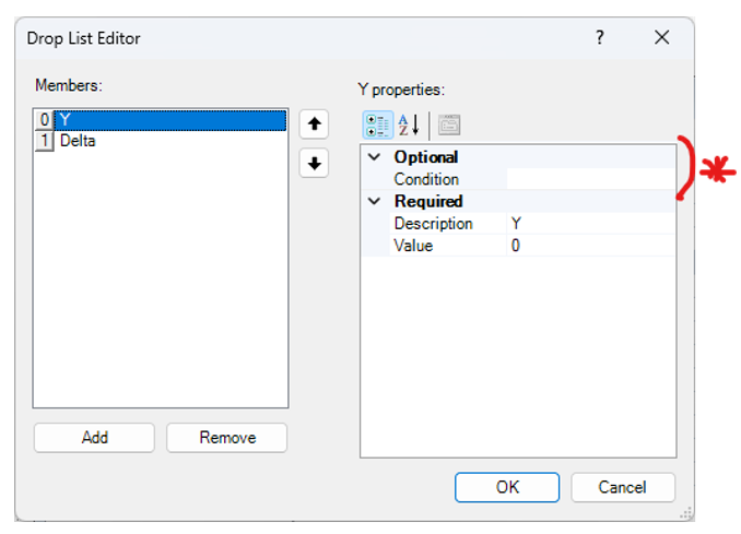
Individual Parameter Choice Field Item Conditional Statements: Conditional statements may now be associated with individual items (collection) in a parameter choice field. This is beneficial when it is necessary to filter the collection list based on the values of other parameters.
Double and Single Quotes in Conditional Statements: Both double and single quotes are now processed properly as part of conditional statements. For example, View == “0” or View == ‘0’.
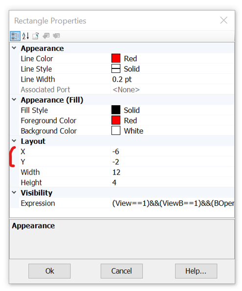
Component Definition Graphics Position: Users may now adjust the position of component graphics directly via their individual properties.
PSCAD System Colours Added: Users may now select PSCAD system colours directly (i.e. integer blue, logical magenta, etc.).

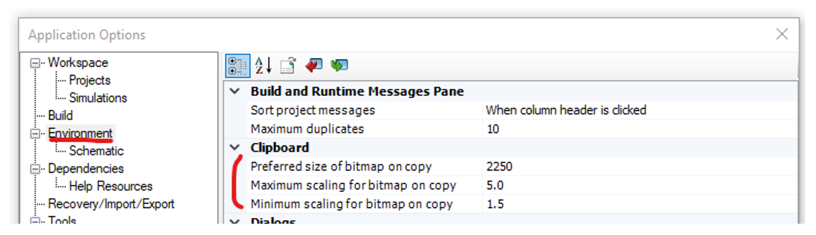
Bitmap Scaling Added to Application Options: New application options have been added to the dialog Environment category, which provide some adjustability to how bitmaps are handled by the clipboard when copied from PSCAD.\
Preferred Size in Pixels
Maximum and Minimum Scaling
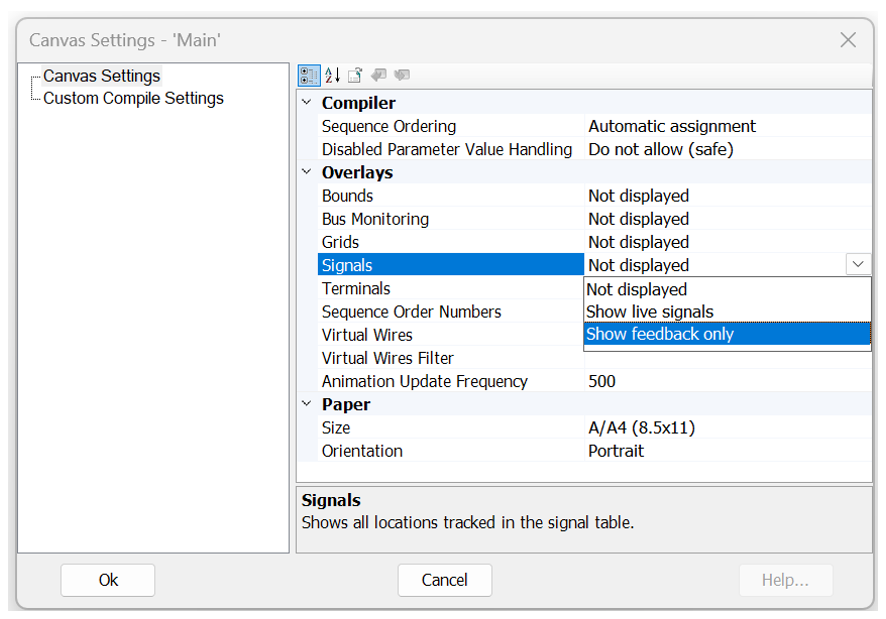
Displaying Feedback Signals: The Signals option in the module Canvas Settings has been updated to include a ‘Show feedback only’ option. This can help provide visual indicators where feedback loops exist on the Schematic.
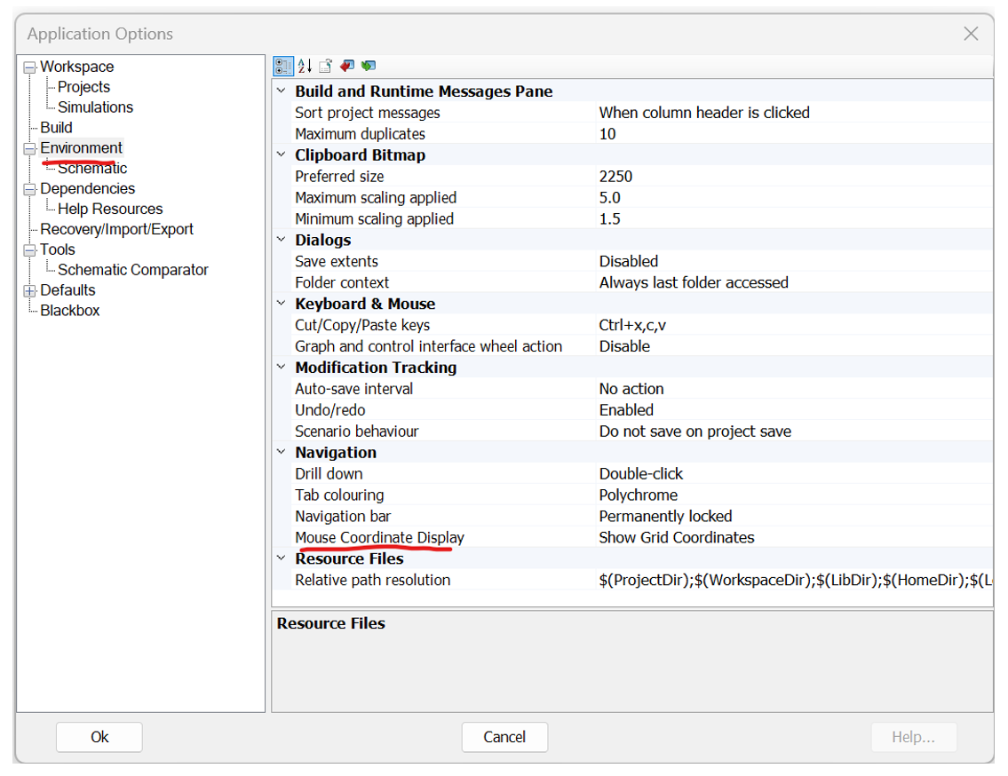
Grid Coordinate View: The coordinate view in the status bar may now toggled between mouse coordinate and grid coordinate view. Grid coordinate view helps when setting up Python scripts that involve direct canvas grid coordinates.
When in wire mode, points can no longer be added to the wire outside the canvas bounds (#8347).
Blackbox-generated object files are now properly copied to the Blackbox folder.
Variables defined in the Computations script segment have been increased from a maximum limit of 8, to 32-characters in length (#8855).
Resource files in the project Resources branch may now be ordered via the resource context menu (move up, down, top or bottom) (#9044).
Print preview mode now allows you to scroll through all schematic canvases available to print (#8793).
The #VERBATIM script directive now works as intended (#9338).
PSCAD now detects Line Constants Program errors, even if the *.tlo/*.clo file was successfully generated (#9089).
Sticky wires now properly undo/redo when moved (#9453).
Cleaned up validation techniques for all parameter types. All parameters now accept literal values, empty values, variables, global substitutions (#9211).
PSCAD no longer crashes when unloading a workspace if one library is dependent on another, and the dependant library is unloaded in such a way as a navigation event happens while the workspace is unloading (#9597).
PSCAD will no longer create additional, empty subsystems in instances where two different buses of are touching (#9609).
In the component definition parameter editor, the move to bottom function now works properly (#9503).
A copied selection is now pasted wherever the mouse is currently pointing (when using ctrl+c/ctrl+v) (#9559).
Sub-sections of the xy plot frame (such as marker sliders) can no longer be cut from the greater pane (#9395).
Separate, redundant menu resources in the xy plot and graph panel frames have been removed (#9394).
Cut/Copy from the context menu of an xy plot now functions properly when right-clicking in the center of the frame (#9397).
'Null Object’ error notification window no longer appears after the deletion of all parameters in a component definition category (#9460).
Deleting a parameter within the parameter editor, via the ribbon Delete button, now functions properly (#9464).
Jumbo canvas size now an available within the transmission line/cable cross-section editor (#9465).
Run button in the ribbon no longer shows empty dropdown when no simulation sets exist in the workspace (#9490).
It is no longer possible (via a convoluted series of steps) for a transmission line or cable to become referenced to an invalid definition (#9462).
Invalid ribbon bar functions are now disabled while within the transmission line/cable editor (#9467).
When a selection containing two or more modules, which are dependent on each other via radio links, the radio link receiver, transmitter definition name is now updated properly (if the transmitter definition name indeed changes) (#9283).
When cutting a curve from an xy plot panel, the actual curve is not removed, instead of the entire xy plot panel (#9577).
Project files that possess an invalid namespace name will now be renamed to a valid name and loaded without interruption (#9647).
Running a Python script containing a pscad.logout() command, no longer crashes PSCAD (#8949).
Component definition script window now properly displays a blank page if no script segments exist in the definition (as opposed to the last viewed script segment from another component) (#9528).
Empty unit parameter values are now allowed in output channel components (#9326).
Printing from the script, map or make file pane no longer crashes PSCAD (#8937).
Application options are now saved to the user profile file when the dialog is closed (Ok button pressed). Previously, application options were only saved on application exit (#9272).
Arrow keys now moves the selection, rather than panning the canvas, when single or multiple components are currently box selected (#8459).
Copying and pasting a port in the component wizard no longer creates a new port without a name (#9712).
Blackbox now properly handles electric networks where no branches exists (but nodes are present) (#9702).
If the signal of a module output parameter is used as an output parameter of a different type in a script function call, the signal is now properly aliased before being passed into the function call (#9515).
PSCAD will no longer crash if the Enable PMR on PNI option is enabled, and the user combines PMR-I using master/slave configurations and radio links, while using PNI transmission line sections (#9564).
Curve menu placement is no longer based on the original view when opened, but the current view (this leads to the menu appearing in the wrong place) (#9590).
An error message is no issued if the user attempts to delete the default global substitution set (which is not allowed) (#9314).
Graph pane speed bar menu, plus some other smaller areas around the PSCAD application have been fixed to display properly on high DPI monitors (#7024).
License workgroup number has been added to the About Box display, for ease in determining license particulars (#8738).
The order the mutual lines are processed in can be arbitrary and may not be what the user expects. For example, if a -section or other component is created from the mutually coupled line, where the order of the transmission segment becomes important, the connection order is not obvious. Connection order information is now displayed on mutually coupled lines (#6738).
Animated substitutions, as well as mixing animated substitutions and static substitutions in conditional statements in a single text graphic, will now draw correctly (#9135).
When recording a script, the automation library no longer rejects the project.save_as(…) argument created as invalid (#9107).
It is no longer possible to enter an invalid equation into a numerical, component parameter type (#9208).
Dragging of multiple selected port in the component wizard is now possible (#9715).
Removed redundant, isolated node build warnings source from the cable interface components (and any others that have nodes only connected via matrix-fill scripts) (#9428).
A ‘Do not show this again’ checkbox was added to the ‘Existing project namespace has been modified’ dialog. This will help when loading large workspaces, where the project filenames have been changed prior to load (filename and namespace needs to be synched for case projects) (#9729).
A simulation run will no longer stall if a plot step is entered that is not an integer multiple of the time step (#9736).
Loading multiple cases at once no longer leads to failed definition reference linking (#9689).
Pasting a control object with multiple scenarios no longer causes the selected scenario (at the project level) for the control to have its values overwritten by the base scenario values (#9705).
When pasting a control object with a scenario into a case that does not have that scenario, the scenario now becomes visible in the scenario dropdown menu (#9701).
If you switch a scenario in the project, while actively viewing controls properties, the properties now update to reflect the change of scenario (#9700).
The contents of Scripts pane will now update if the *.py file being viewed is edited and saved externally (#9768).
PSCAD no longer issues a warning when an integer parameter is entered as a valid negative value (#9780).
Project and application-level substitutions (ex. $(Namespace)) are now available anywhere that global substitutions are used (#9786).
PSCAD will no longer crash when using Python to blackbox a module, and the blackbox creation fails (#9800).
Using the Esc key to close any of the various text file viewing panes (ex. Scripts, Map, Make, etc.), no longer closes the pane view permanently (#9810).
PSCAD no longer crashes if the description of a module is more than 79 characters long (#9773).
Added a single, customizable dialog to handle multiple simulation set tasks that are set to launch from an integrated debugger. This alleviates the need for multiple dialogs (#9775).
Animated graphics can consume a significant amount of processing time in a simulation, especially when an expensive to draw object like a graph is sitting on top of an animated component. This specific situation is now handled more intuitively, resulting in simulation speed up (#9834).
Invalid EMTDC constant PI changed to the valid PI_ in the script segment, EMTDC Constants symbol list (#9431).
A choice parameter default value list on a high DPI monitor, while editing a component definition, will now display properly (#9611).
PSCAD now validates its state on startup and on application settings change. If any file required for startup is missing, the user is now notified (#9842).
PSCAD now issues a build warning if duplicate sequence numbers are detected (can occur in manually sequenced modules) (#9843).
Opening a PSCAD case with a curve id='6710', no longer causes an unexpected New Layer dialog to appear, interrupting the case load (#9877).
When specifying a snapshot in the Project tab of the ribbon control bar, the proper ‘Save As’ dialog is now opened (rather than the ‘Open’ dialog) (#9831).
Rotation of text labels within the component definition graphics editor now function properly, including hotkeys and ribbon buttons (#9901).
A transmission segment is no longer forced to re-solve on a simulation re-run after the project file is saved, and there were no modifications made to the transmission segment (#9723).
Unmodified, mutually coupled transmission segments are no longer forced to re-solve whenever the simulation is re-run (#9846).
Undo/redo now functions properly when adding/removing control interfaces to/from control panels, as well as adding/removing graphs to/from graph panels (#9924).
It is no longer possible to drag cable or t-line cross-section definitions from the project definitions list, onto the schematic canvas (#9926).
The component wizard now properly releases a newly created, floating component (attached to mouse pointer) if the user decides to go back to the wizard to re-create it (#9912).
A newly created component definition (in the project definition list), using the component wizard, is now properly removed/added when the action is undone or redone (#9881).
It is no longer possible to add a dead curve to a graph from a component that is not an output channel (#9907).
Fixed some minor issues with folder access tracking functionality (#9930).
Transmission line and cable definitions are now properly relinked to their respective instances following a definition name change. This had caused issues with instance parameter changes not sticking (#9826).
Inter-project paste transfer operations may now be properly undone or redone. Previously, undo/redo simply deleted the instance, not the definitions (#9929).
Components newly created via the component wizard or blackbox may now be undone while in a floating state (includes both instance and definition) (#9932).
A newly blackboxed component is now properly removed/added when the action is undone or redone (#9940).
PSCAD now provides a build warning if two or more identical sequence numbers are detected on a manually ordered, schematic canvas (#9843).
Ctrl + left click to select/deselect multiple schematic canvas objects, now functions properly (#9816/#9951).
EMTDC will no longer dead lock if ALL the following criteria are met: There are multiple co-simulation components in a single case; each co-simulation component is connected to the same client id, but different channels; the co-simulation timestep is not the same as PSCAD; the order in which PSCAD processes the co-simulation components is different than the tool.
Components existing as part of an invisible layer, no longer appear visible when printing the schematic canvas (#9954).
Recording a script in PSCAD can produce the line: task = simset.add_task("project_name"). This function will no longer fail when the script is run (#9976).
Two or more instances of PSCAD, each running a project of the same name in debug mode, will now launch multiple instances of MS Visual Studio environments (#10010).
Wire mode (and other selection modes) now automatically shut off on creation of a component (ex. clicking a new component button in the ribbon) (#9949).
Implicit casting is now properly performed when casting any signal type to complex, or from a complex-type signal to a logical (#9963).
Undo/redo now functions properly after component nudging operations (arrow keys) (#8081).
Adjusting sticky notes arrows now mark project as dirty and are included in undo/redo (#9910).
Mapping of x-nodes now works properly when there are multiple x-nodes of the same name, but different enabled values (#9996).
The Echo runtime parameters and options checkbox now functions properly and will display the runtime parameters in the Runtime Messages when checked (#9978).
The co-simulation interface will no longer stall if the co-simulated application exits early. When finalize is called, it will resend the last information with an indefinite expire time. This will ensure that the simulation can continue to run on the last information sent (#9975).
Blackbox now checks for the presence of complex signals. If the blackbox compatibility option is set to any version prior to v5.0.0, blackbox will fail, as complex signals are supported only in v5.0.0 onwards (#9984).
A plot step smaller than the time step can no longer be entered in the ribbon projects tab. If such a plot step is entered, it is immediately adjusted equal to the time step (#8342).
Fixed a rare situation involving a source contention going unnoticed by the netlist compiler. If a data label source by an import tag, is placed on a signal generated by another import tag, no error is issued (#10081).
Compare tool definition lists are now presented in alphabetical order (#9970).
The run button now remains disabled when selecting to start externally from an integrated debugger (#9936).
The consolidator now supports multiple EMTDC platforms. So, when *.dll files are involved, all required *.lib files are included as resources (#10062).
Custom layer settings are now properly saved with the project (#10140).
Right-clicking while dragging an object on the schematic canvas no longer leaves artifacts (#7749).
In the specific instance where a module with a fixed electrical node port, that is connected to an x-node inside on its schematic canvas, which is attached to a switched electrical node, is blackboxed, the node defined by the port will be labeled as a switched node. Prior to this release, there was an inconsistency between a compiled module and a blackboxed module (#10182).
Blackboxing any module containing a multimeter that uses a $VDC:A(1):A(2) statement (i.e. is measuring an instantaneous voltage), will now produce correct, measured results. I simple indexing issue was discovered and corrected (#10190).
Drawing layers (incl. quick enable/disable) now function properly within the t-line/cable editor canvas (#10196).
The parameter grid will now enforce edits if switched to a new parameter grid view, while still in edit mode on the previous view (#10208).
Blackbox now properly parses directives, such as $#DIM, in the model-data sections of custom components existing in the module being blackboxed (#10160).
Paste rename will now scan the original name for an existing suffix number and use that as its starting point (instead of simply appending a ‘_#’). For example, Sig_1234 becomes Sig_1235 (#10084).
Renaming the definition of a transmission line or cable, from the workspace tree, no longer causes instances connected to it to forget their parameter values (#9903).
Component graphic objects can now be pasted properly after copying to the clipboard (#10231).
Copy/paste functionality now functions consistently with previous versions of PSCAD: A selection always takes precedence over hover when copying. Hover only (with no selection) will copy the hovered object (#10232).
Python scripts containing Unicode characters will now be displayed properly when viewing in the Scripts pane (#10240).
Fixed erroneous results that can occur when using the comparison tool (#10248).
Mutual coupling now functions properly when including the ‘Simplified Underground Cable’ component (#10133).
If a sticky wire is connected to a bus component AND other components or a non-sticky wire, the bus is now given connection priority. So, the sticky wire will only move with the movement of the bus, if a bus is present at the connection point (#10207).
Cleaning from the context of the simulation set, now properly clears the build messages in each simulation task (#10234).
A negative integer is now accepted as a valid integer when entered in the integer constant tag component (#10053).
Annotations and sticky notes are now supported properly on T-Line and Cable cross-section canvases. Previously the presence of either component would cause solve errors (#9409).
The C-language interface code, auto-generated by the Component Wizard, now uses ISO C binding when linking Fortran files, as a cleaner, simpler way to bind to the C then the previous manual binding method (#9270).
MANA element/index order is now consistent and correct between blackbox-generated Fortran and the project Data files, when multiple MANA components appear on the same module canvas being blackboxed (#10353).
The blackbox option allowing users to set a specific target project (i.e. one other than the current project) has been removed entirely. This functionality can be manually performed by copying blackbox-generated definitions and resource files to another project (or use Python) (#9059).
MANA branches are now treated properly by blackbox when MANA components exist within a multiple-level module hierarchy (#10336).
Wires are now drawn in the correct position following a reversal of its vertexes (#10307).
Switch and dial actions, during Python script recording, are now properly formatted (#10396).
PSCAD will now auto-select a valid Fortran compiler in instances when the user has installed an updated version of PSCAD, but the previous version user settings file was set to a compiler that is no longer supported (#9350).
When using the create compiled library feature (or when blackboxing), PSCAD now chooses the least recent Fortran compiler, within a compiler family, when generating an *.obj or *.lib file. This ensures that the compiled file is compatible with all compilers in that family (#10442).
Plot step display in the ribbon control bar will now change accordingly if the plot step is changed via the var_plotstep component (#10126).
NDProtocol handles are no longer accumulates when running very large PNI simulations consecutively over RDMA. This accumulation was causing performance issues (#10507).
PSCAD no longer crashes if the meta-file (*.psmx) is corrupted (#10572).
On paste-transfer of a component that references a definition without a namespace, the components definition reference is now correctly resolved (#10636).
Transmission segment namespace reference is now properly modified when the namespace name changes (#10625).
When converting *.psout format to older *.out format, the converter now exports properly with 10 traces plus a domain, rather than 9 traces plus a domain. This caused a serious issue when importing into Enerplot (#9539).
*.psout files may now be read from or written to by multiple programs simultaneously. This means, for example, that you may now update *.psout file data in Enerplot, while PSCAD is generating the data for the same file (#9695).
When writing EMTDC output as *.psout format, while using the GFortran compiler, stored animated graphics information is no longer corrupted (#9682).
Active graphics traces are no longer overwritten after 128 active graphics actions, when stored within the *.psout file format (#9770).
The PSOUT reader now overrides the Microsoft Windows Regional Settings on Export. Regional settings can lead to invalid files, as the format may not match expected file format (ex. using ‘,’ instead of ‘.’ as a decimal) (#9995).
The PSOUT Utility output converter now properly formats *.out file names identical to that written by EMTDC: Specifically, with regards to the file number increment, when multiple *.out files are generated (#10027).
Subsystems Solved in Parallel: Subsystem solving is now multi-threaded, meaning several subsystems are solved simultaneously on different threads, enhancing simulation speed of multi-subsystem projects.
Improved Ideal Branch and Transformer Processing: Ideal branch and transformer processing is now improved by utilizing cached memory for some of the computations, enhancing simulation speed. A speed improvement is specifically noticeable in projects that contain many ideal branches and/or transformers.
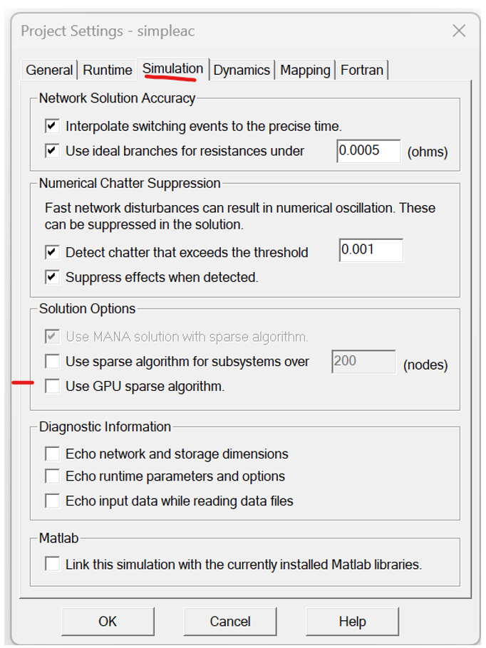
GPU Sparse Algorithm Enabled for EMTDC: EMTDC may now utilise GPU processing power via an alternative sparse algorithm, in addition to the legacy sparse algorithm already inherent to EMTDC. To enable this feature, simply toggle the associated project setting.
Multi-Rate (or Multi-Timestep) Transmission Line Upgrade: The transmission line configuration component has been upgraded to support multi-rate, parallel network interface (PNI) simulations (i.e. different simulation timesteps at each of its ends). There are no additional parameter settings to configure. Simply connect the PNI simulation as you normally would and run.

Note that at the time of release, multi-rate functionality is only available when using foreign ends. In other words, only PNI simulations that are run from within a single instance of PSCAD may make use of multi-rate (PNI simulations between multiple instances of PSCAD, using alien ends are not supported). The only other limitation is that the transmission line model being used must be selected as the Bergeron model.
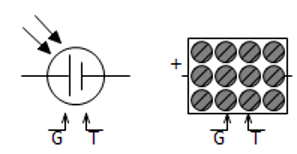
New Photo-Voltaic (PV) Source: A newer PV source model (photovoltaic_source2) is added to the master library. Unlike its predecessor, this component can take typical data available in datasheets. The data required by the previous model was not easily available to the user.
New Synchronous Machine with Simplified Input: An alternate synchronous machine model with a simplified interface, is included in the master library. The model uses the same routine as the original synchronous_machine model; the difference is only in the interface.

New Universal Induction Machine with Simplified Input: This component is a universal version of the induction machine model (introduced with v5.1.0), which can be used to model either a wound-rotor or a squirrel-cage induction machine. Data input via parameters has also been simplified somewhat. It also supports Type 40 format.

All Classical Transformers, Including Auto Transformers, Updated: All classic transformers in the master library (except for the 1-Phase, N-Winding Transformer) have been updated to include a more simplified set of input parameters.
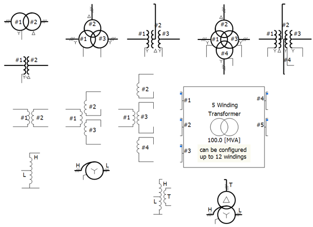
Frequency/Phase/Magnitude Meter Component: New meter component added that calculates the fundamental frequency (f), RMS magnitudes (V), and the phase angles (Θ) of a single-phase or a three-phase AC voltage input.

New PID Controller Component: A new component that models a Proportional – Integral – Differential (PID) controller is added to the master library.

New Hysteresis Controller Component: A new hysteresis controller that takes an input and produces an output based on predefined thresholds, has been added to the master library. The component switches the output between two states when the input crosses these thresholds, preventing rapid fluctuations..

New Over and Under-Excitation Limiter Components: Two new components that model over and under-excitation limiters (conform to the IEEE Standard 421.5-2016) have been added to the master library.

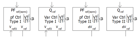
New Power Factor and Reactive Power (VAr/PF) Controller and Regulator Models: Two new components that model Power Factor and Reactive Power (VAr/PF) Control (conform to the IEEE Standard 421.5-2016) have been added to the master library.
New COMTRADE Recorder Component: The old RTP/COMTRADE Recorder component has been replaced by a new, COMTRADE only component in the master library. All references and functionality to the Real Time Playback (RTP) product, and COMTRADE 91 formats have been removed. Only COMTRADE 99 formatted output is supported.

Single-Phase PI Section: A new component definition called pi_section has been added to the v5.1 master library. This component can be used as either a single-phase or three-phase pi-section.
![]()
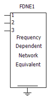
FDNE Component Upgraded to Use Optimised Matrix Storage: A new version of the FDNE component definition called ‘fdne2’ has been added to the master library (the original ‘fdne’ definition is now deprecated). The new version includes an optimised storage matrix.
Moving Average Filter: A new component definition called moving_average has been added to the v5.1 master library. Given a defined moving window and number of samples within it, this component takes a moving average of its input signal.
![]()
New Duality-Based Transformers: Two new, duality-based transformer components have been added to the master library: The duality-based, 3-Phase 3-Winding and the 3-Phase 4-Winding Transformers.

New Pipe-Type Cables: Two new pipe-type cable components have been added to the master library, both based on the existing pipe-type cable: The first is a pipe-only, and the second, a simplified pipe-type component. Both are added to alleviate some headaches in data entry.

Three New PLL-Based Examples Added: Three comprehensive example projects, which demonstrate the usage of the PLL master library component, have been added to the list of released examples. They reside within the CSMF/PLL folder.
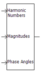
IEC Standard Input Added to the Harmonics with Different Magnitudes Component: The IEC Standard has been incorporated into the input format for the 'harmdiffmag' component. Specifically, the format follows IEC Standard 61400-21-3, specifically Tables 1 and 2 on Page 23.
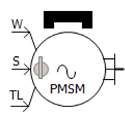
New Data Entry Format for the Permanent Magnet Machine: The PMSM now includes two different data input formats: Equivalent Circuit and Dynamic Model. Equivalent Circuit format represents the electrical characteristics of the machine using parameters like resistance (R) and reactance (X). Dynamic Model format describes the time-varying behaviour of the machine, including key aspects such as transient time constants and transient reactance.
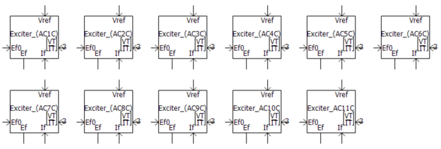
AC Exciters (2016) Update: The AC exciter component has been updated with some minor parameter changes.
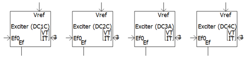
DC Exciters (2016) Update: The DC exciter component has been updated with some minor parameter changes.
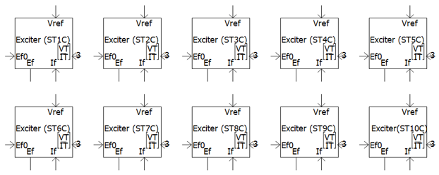
Static Exciters (2016) Update: The Static exciter component has been updated with some minor parameter changes.
Power System Stabilizers (2016) Update: The Power System Stabilizer component has been updated to conform to the IEEE Standard 421.5-2016.

RMS Option for External Control of Voltage Source: External voltage control in this component may now be accomplished via a line-to-line RMS signal, in addition to the existing line-to-ground peak format.

Greek and Math Symbols Displayed in EMTDC Constant Tag: PSCAD V5 supports Unicode, so the graphics in the emtconst master library component have been updated to display actual Greek characters and math symbols, instead of spelling them out.
![]()
Twist Component Compact View: The new Twist component now has a compact view that matches with compact breakout, as well as a single line view. An additional option is also provided to break the nodes into two, distinct sets by inserting an ammeter between them. This would be helpful when both ends are connected to breakout components.

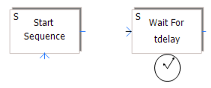
Sequencer Start and Wait Components Now Edge Triggered: The Sequencer Start and Sequencer Wait master library components have been modified to function on and edge trigger, rather than a level trigger. This was done to resolve a sequencing issue that could occur under the right conditions.
#COSIM Directive in Co-Simulation Component: A new directive has been added to the co-simulation component to act as an alternative identifier to the component definition name. This allows users to create and use their own, custom co-simulation components.

#COSIM $client_id $channel_id $s_dim $r_dim
Where:
1. Client ID: The ID of the application, with which it will be co-simulating.
2. Channel ID: The ID of the channel in the application.
3. Send Size: The size of the data that this component will send to the other application in terms of total of real numbers.
4. Receive Size: The size of the data that this component will receive from the other application in terms of number of real numbers.
Current Measurement Added to RLC Branch Components: Components var_impedance, rtcbranch and fixed_load1 are modified to provide current measurement through the branch as an internal output. The graphics of each component was also updated to show the direction of current measurement.

Default Capacitive Branch Behaviour in Variable Impedance: The var_impedance component has been modified to give the user a choice on how to treat zero capacitance as a short-circuit or an open-circuit. It is defaulted to a short-circuit to provide backwards compatibility with PSCAD v5.0.
![]()
Graphical Display Indicates Conversion of Output to Nearest Integer: Some components in the master library (ex. compar, compare, range, var_pot, var_switch, etc.) have the option to convert the output to the nearest integer. Now, a graphical indicator (a small blue box) when this option is applied.

Added new parameter to the dependent sources to allow an easy way to invert the components direction up or down (#9242).
The FFT component now has a proper id call, the lack of which was causing generated messages to point to other components (#8944).
The FFT component now limits the tracked frequency to the maximum permissible, set by the project time step, avoiding a runtime error (#8966).
The Multimass component now supports fixed power share, in addition to fixed torque share (#8837).
Fixed an issue with the PGBNAME function in EMTDC, which caused a simulation to get ‘stuck’ when many output channels exist in a project (#9673).
Unrealistic saturation parameter data in the AC and DC exciter components is now caught and the user is notified with an error message (#9919).
When a constant signal is used as an analog input to the COMTRADE recorder component, the COMTRADE file generated is now correctly written (#9913).
The correct information message and time step value are now provided in situations where the COMTRADE recorder component’s recording time step is less than the simulation time step (#9909).
When a multiple run with a tandem line, with other lines present is launched, the simulation no longer fails on the 2nd run (#9934).
The FWAV22 routine and its variants no longer creates runtime message flak for minor imbalance of phase magnitudes (caused a negative influence on execution speed) (#9942).
The fault component now displays N instead of G if the fault neutral point is not directly grounded (ex. A->N instead of A->G) (#9855).
EMTDC no longer emits multiple PSCAD_AGR2 statements in runtime messages (#9961).
Interpolated output of the delay component no longer gives values outside the input range, when subjected to certain conditions (#9255).
A chatter removal step is now only applied, when necessary, when starting from a snapshot. Previously persistence of this step created a slight difference in results (#10046).
The UMEC transformer model now produces a correct, user-supplied saturation curve (#2825).
Both source models 1 and 2 are now giving the full voltage when the ramp-up time, or time constant, is set to zero (#9977).
The computed matrix sparsity limit has been increased by upgrading to INTEGER*8 from INTEGER*4 (which could result in errors if the number of nodes per subsystem is close to 50,000) (#10162).
An issue with the LOGICAL storage incrementor has been corrected in ST1C exciter component (#10144).
A new choice parameter was added to the surge generator component to allow specification of how maximum steepness is defined, when configured for the CIGRE standard. This allows for arbitrary changes in peak current amplitude (#6352).
The current source component default parameter values have been modified to be more realistic (#7229).
GFortran compilers no longer fail when the Fileread component is set to output the last value, or interpolate, and the simulation length is longer than the data file (#6358).
The FDNE order is now properly defined when the component set to input user-defined ABCD parameters (#7153).
An additional voltage option is added to the synchronous machine component. The voltage rating may now be specified as line-to-line or line-to-neutral (#4492).
The parameter Capacitor Leakage Resistance for the MMC Full Cell and MMC Half Cell components have been updated to allow variable signal input (#6613).
The Ramp Up Method parameter in both the 3-phase and 1-phase voltage source model 1 can now be selected as First Order Lag or Linear (#10029).
The Frequency Scan component will now properly process when t-lines or cables are present that are configured to use manual data entry with multiple frequencies (#10057).
The MMC Half Cell component has been fixed so that the capacitors of each module can be initialized correctly, as set in the parameter 'Sum of Capacitor Voltages at Time zero' when 'Partial Blocking' is enabled (#10132).
Fixed an insufficient storage allocation issue in the ZDelay component script, which would arise if several delay components were being used (#10146).
The FDNE now functions properly when used with multiple frequency scanners and FDNEs (#8774).
Line current measurement parameters in the 3-Phase, 2-Winding Transformer are now always enabled (and give the correct value) regardless of the winding configuration (#10264).
Upper value maximum of leakage impedance has been relaxed to allow more realistic data entry (i.e. > 1.0 pu) in some applications (#10194).
The xy transfer function component expects x-axis data to be entered in ascending order. However, no check was being done to inform user if this is not so. A check has now been implemented to produce a warning (#10261).
The Rank component now gives the correct output when used inside BEGIN routines (#10311).
Spring constant entry in p.u. for the multi-mass component now provides accurate input, as verified via eigenvalue analysis (#10250).
The z-domain, nth order transfer function component no longer encounters an error when handling multiple dimension input signals (#10394).
The 'Conductors to Eliminate' parameter of the Pipe-Type Cable component will no longer affect the cable calculation even if it is disabled (#10471).
Detailed output file viewer now displays the correct units in the detailed output drop list (#10451).
Exciter components no longer allow SCL (oel) to go as take-over and SCL (uel) to go to the summation point at the same time (not allowed according to the standard) (#10441).
EMTDC results are no longer slightly different when a project is started from a snapshot, compared with one started from the datafile (or t=0.0). Logic for an additional interpolation step is now performed only if needed (#6225).
The ST6C-type exciter now properly accounts for the influence of the PSS input (#10530).
Fixed an error in parameter visibility logic in the xfmr_Nw transformer: The leakage reactance (4-7) parameter was never visible when the transformer is set to 7 windings (#10635).
Some projects no longer generate linking errors related to frexp, which is included in bhlibucrt.lib (from Visual Studio) and libmmt.lib (from Intel) (#10666).
The frequency scan master library component now works properly when there exist t-lines or cables in the network, configured to use the multiple-frequency, manual-data entry method (#10673).
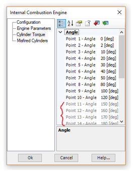
The ic_engine master library component no longer fails if number of misfiring cylinders is greater than 3 (#10778).
MoM-SO Method Added: Users may now opt to use MoM-SO methodology, instead of the classical formulas, to more accurately solve cable constants where proximity effects in the conductors are prominent.
MoM-SO is a semi-analytical method used to compute cable parameters more broadly, considering proximity effects for the correct prediction of electromagnetic transients in cables that are placed close to one another, such as submarine cables.
MoM-SO is controlled in PSCAD via the Additional Options component: An optional component that is placed on the cable cross-section, along with the model, ground return, and the cable itself.

Modified formatting of LOAD FLOW RXB DATA to show three decimals, instead of two (#9987).
Pi-section component creation now functions properly when the line/cable is set to manual data entry at multiple frequencies (#10058).
Fixed a singularity problem that would occur when underground cables and aerial lines exist within the same right-of-way, due to an incorrect starting index (#10156).
Long-line corrected data entered in the Manual Entry of Y,Z component, is now handled properly (#9357).
When the Bergeron line model is used with the Manual Entry of Y,Z component, it is now considers the frequency for loss approximation properly, in the generated constants (*.tlo) file (#9989).
When the Bergeron line model is used with the Manual Entry of Y,Z component, it is now considers the travel time interpolation and reflectionless line properties properly, in the generated constants (*.tlo) file (#9938).
The LCP now issues a proper error message when a user attempts to solve a transmission segment contained the Frequency-Dependent (Phase) model with the Manual Entry of Y,Z component, when the Manual Entry component is not set to multiple frequency input (#10201).
The correct port numbers are now used in the Matrix Fill section when the transformer is set to delta-lead configuration. This is for both 3-phase, 2-winding and 3-phase, 3-winding models (#10326).
Installed Intel Fortran compilers are now listed in order of their release date when viewing selecting a compiler (#10364).
All support required for the GFortran 13.2 compiler has been added (#10005).
All support required for the Intel Fortran 19.2 compiler has been added (#10041).
All support required for the Intel Fortran (ifx) 2025 compiler has been added (#10314).
All support required for the Intel Fortran 2024.0 OneAPI compiler has been added (#9878).
A new setting, when enabled, will set a license certificate to be returned only when the last running instance of PSCAD, attached to that certificate, is closed (#10325).
A new setting, when enabled, will set PSCAD to first check to see if a license certificate already exists, before trying to acquire a certificate. This will help alleviate ‘stuck’ licenses in many scenarios (#10320).
Release v5.0.2 is the second maintenance update to the PSCAD V5 product. This release includes bug fixes, deficiency fixes and minor enhancements.
Load Speed Greatly Enhanced: Dozens of speed optimisations are now implemented in PSCAD with the primary goal to enhance project load speed. Given our very large testing workspace, containing 100+ projects as a benchmark, speed improvements are as follows:
v5.0.0: 11 minutes to load
v5.0.1: 7.5 minutes to load
v5.0.2: 2 minutes to load
Python Automation Updates: Several updates have been made to the python automation capabilities in PSCAD:
Library project command Create Compiled Library (*.lib) is now included.
Edit Reference | Namespace and Definition Name now automatable.
Added the ability to automate the modification of definition settings (<definition>.parameters()).
Added the total number of definition instances as an attribute (<definition>.instances).
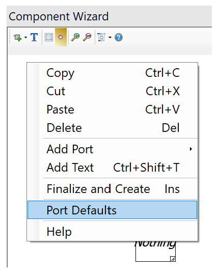
Component Wizard Port Defaults: Users can now set default port properties that are applied when creating new ports in the component wizard.
Signals generated from sequencer components are now created correctly (#8965).
A PNI simulation will no longer stall and fail if two, alien or foreign-end t-lines possess identical names (in different projects) (#8968).
The *.infx, EMTDC output information file now includes output from outside library projects (#8969).
Password type parameters will now accept empty strings (#8899).
When you switch views between projects, the zoom level in the graphs is no longer lost (#8125).
When panning a schematic canvas using Ctrl + Shift + left mouse hold, the panning no longer stops if the mouse pointer goes outside the window frame (#8970).
Zooming the schematic canvas is no longer forced about the canvas center (#8979).
When moving any group of components, or a selection, the project is now properly marked as modified (#8978).
The *.psout EMTDC output file is now created properly when starting the simulation from a snapshot (#8996).
Application will no longer crash if a terminal is missing a node, or a node is missing a signal. These events can be triggered by a datatap component output being attached to an electrical node (#9004).
Build messages, when attached to a support request (from the support request frame) are no longer un-intelligible (#8956).
The make utility no longer emits garbled messages to the build message window (#9035).
Build messages sourced from module components whose definition is stored in a library, are now routed to the build message window of the case project being compiled, not the library project (#9040).
PSCAD will now properly bind to the socket when using a non-ASCII hostname (#9015/#9032).
The text file created to describe mutual Z and Y matrix data for mutual coupling is now properly formatted (#9016).
Debug-related project settings now properly persisted following the creation and then saving of a new project (#9067).
Graphs no longer erroneously mark the project as modified while the project is opening (#9006).
Application will no longer crash if the build process is terminated at certain times (#9076).
Application will no longer crash when selecting two non-module components to launch the schematic comparison tool (#9093).
Support request attached build messages file is now formatted properly and readable (#8956).
Fixed memory leak in blackbox algorithm (#9069).
Diagnostic information within the project settings is now properly handled on creation of a new case project, and hence the settings will now be saved with the project properly (#9067).
Application no longer crashes upon stopping the simulation with the application option ‘Copy .dll to local folder (gf46)’ enabled (#9076).
Disabled the ability to invoke the module comparison tool via non-module components. Such an operation would lead to an application crash (#9093).
25. Fixed sporadic crash that can occur when editing component parameters and accepting changes very quickly (#9134).
Resource files now update properly following a modification within an external program (#9123).
A proper build message is now displayed when using the programmable pause component. Also the status bar run time is updated to the exact pause instant (#9166).
The ComFab now properly deletes the master connections when closing the connections after a run. This issue had sometimes caused memory handles to build up and leak (#9170).
Component properties now properly formatted as CSV when selected as such, when exporting to file from view properties dialog (#9196).
Scatter plots no longer cause PSCAD to crash if they have data that is not initialized properly (#9219).
Column headers are now properly quoted when exporting component parameters to a *.csv file. Previously, if the parameter description contained a comma or other character, it could corrupt the *.csv file (#9198).
Component parameters set to ‘invisible’ are now properly ignored by the script compiler (#9216).
If a real, global substitution is used within an integer-type parameter, a type conversion warning is now properly issued (#9111).
Tabs are now properly rendered by sticky notes (#9132).
It is no longer possible to set a global substitution name to an empty string by deselecting pane while the name is empty (#9213).
The #COMPONENTID script directive is now properly supported when saving projects as v4.6 format (#9202).
R, X and B values are now properly displayed in solved t-line and cable properties component parameters (#9228).
License certificate expiry warning message now displays time to the minute, if necessary (#9231).
New component instances no longer lose their definition reference, if the definition exists in an external library and the name is changed prior to it being instantiated (#9232).
Schematic canvas zoom from the ribbon buttons now functions more consistently: For example, if a component is selected, zoom will be centred on that. If not, the canvas view centre point will be the focus (#9174).
Quick disable graphic now properly supersedes layer-based disable to match the actual disable priority (#9110).
Overlay graphs created directly from an output channel component, now inherit the min/max, y-axis settings from that component (#8763).
Vastly improved drawing speed during simulation and zooming, when curves are set to points-style (#9244).
Greatly improved simulation run speed when zoomed out and viewing many components (such as buses) that utilize component state animation (#9238).
If a mutually coupled line has one end not attached to the same sub-system then it was possible, depending on arbitrary ordering of nodes, that the t-line would wind up coupled to two different sub-systems and would result in DSLINT errors from EMTDC. This issue has been fixed (#9246).
Resources in the resources branch of library projects are now included as part of a case project build, even when the resources are not linked to a dependent module in that build (#9257).
Choice parameter descriptions that contain '=' (and other) characters will no longer get truncated when displayed within component graphic labels, when using the getChoiceText(…) macro (#9250).
Component wizard no longer spills graphics from sliding tray when pane is very small (#8275).
The Paste menu item no longer appears disabled when copying/pasting a component parameter from one component to another, while in component edit mode (#9300).
Fixed an issue where PSCAD can stall during a multi-run simulation, where a significant amount of back and forth communication occurs. The stall was caused by a ‘race condition’, which would result in a corrupted communication buffer (#9312).
When drawing curves with a filled style with best speed drawing, if the curve itself is outside the Y bounds of the graph aperture, the curve will now be drawn correctly (#8509).
Save as v4.6 (from V5) now properly exports V5 format Global Substitutions to the v4.6 format (#9275).
All functions in the schematic tabs context menu now function properly (ex. Close all tabs to the right) (#9339).
C-files auto generated by the component wizard no longer contain invalid line endings, if the component is created through the copy-paste mechanism. Fortran files auto generated by the component wizard no longer contain invalid directives (#9343).
Workspaces containing many cases (hundreds) no longer take an inordinate time to load. Optimization techniques have been implemented to greatly reduce load and layout time (#9364).
T-lines and cables can now be removed from a layer via its context menu (#9365).
After creating a new module instance, the canvas view position in the module no longer defaults to view position of the module, from which you are navigating. That is, the default canvas view is always top left and default 150% zoom (#9366).
The Paste context menu item now functions properly in the component definition graphics canvas (#9347).
When selections are nudged or dragged outside the visible area of the schematic canvas, the canvas will now auto-scroll so that users can see what they are doing (#8666).
Shrunken graph frames, copied and pasted as metafile format, no longer display graphs outside the graph frame view (#9402).
Graph frames scroll bar grips are now painted so as to be more identifiable. Previously the grips were difficult to see, as they were painted the same colour as the graph frame panel (#9399).
PSCAD will no longer crash if a module definition is given a new name, while the module is being viewed (9435).
PSCAD will no longer fail to launch if the current operating system has an IPV6 address set as the priority one (9432).
Viewing the ribbon File tab is faster now when there are deleted files, or file located on a slow network drive, in the previous file lists (#9443).
PSCAD will no longer crash on compile because of an invalid cable or t-line definition (#9461).
PSCAD will no longer crash when the OK button is pressed on an empty component parameter dialog (#9459).
Blackbox now properly handles global substitutions placed in non-supported, literal component parameters inside the module being blackboxed (#9487).
The workspace pane view no longer ‘jumps around’ when navigating a project tree containing a large number of projects (#9187).
When a scenario has been modified an attempt is made to unload project without first saving the scenario modification, the modified scenario is now saved to the project properly (#9504).
Added support for MATLAB versions R2009bSP1 (7.9.1), R2022a (9.12), R2022b (9.13) and R2023a (9.14) (#9519/#9521).
PSCAD no longer crashes when unloading a project that causes a navigation event to take place (#9513).
Fixed erroneous duplicate namespace message that could pop up when editing project settings (#9557)
The FFT component now limits the tracked frequency to the maximum permissible, set by the project time step, avoiding a runtime error (#8966).
When filter coefficients A1 and A2 set to 0.0 in the PSS1A stabilizer component, the results are now the expected (#8967).
When using i-lambda data entry in the saturable reactor component, with the number of points set to 4, the 4th point for flux linkage is now properly visible (#9080).
The ST4B exciter component no longer displays transient behaviour at initialization under some specific configurations (#9054).
Entering a zero as the initial operating head in the hydro turbine (hy_tur) master library component, no longer produces NaN runtime error (#9092).
Snubber circuit graphics on the peswitch component now disappear as expected when the snubber circuit is disabled (#8951).
7. Entering non-zero copper losses no longer results in the secondary signals being zero (#9197).
The visual appearance of the sample and hold component is now correct when two inputs are selected (#9161).
The surge generator component is now compatible for use in PSCAD v4.6.
Fixed an undefined parameter used in script error in the pipe-type cable component (#9220).
Wound rotor induction machine: Leakage saturation data entry is now enabled if leakage saturation is selected on both stator and rotor. Number of data points in the leakage saturation is now used in the script section (#9258).
Dependent sources now produce correct results in the 2nd and subsequent runs in a multiple run (#9293).
The string to save channel titles in the multiple run extra recording component are now sized correctly (creating a buffer overflow situation) (#9310).
Fixed a code error in the MMC half-bridge model where variable VR1 was used in place of VR2 (#9292).
The DC4B exciter component now properly creates the port associated with the VS input, when the stabilizer input is enabled (#9290).
Fixed a spelling error in the coupled_3lines component script code (#9282).
The fixed load model now exhibits the proper behaviour outside the limits of 0.8 and 1.2 pu (#9094).
Under certain conditions, the scaling value in the scaling component had to be N+1 to get the scaling of N. The component now emits an error message if -1 is given as the scaling value (#9240).
The fault component now properly turns red when a fault is activated (#9383).
The duality transformer component, with taps enabled, now produces the correct frequency scan output (#9376).
In certain situations, the frequency scanner component no longer gets locked into an unrealistic value (#9382).
The duality transformer component no longer creates bad code when BH data with dimensions is chosen as saturation method (#9414).
EMTDC singularity checking has been tightened. Now it detects and warns the user that results may be incorrect (#9413).
A continuous zero-value input no longer creates unreadable data in the COMTRADE component output (division by 0 issue) (#9445).
When recording a script, and the size of a graph frame is changed, the proper command is now scripted: frame.size = (##, ##) (#8982).
Project settings can now be modified when using Python to launch PSCAD on a clean machine (ie. where the user settings file does not exist) (#9136).
Application no longer hangs/crashes on run after switching the Fortran compiler using a Python script (#9115).
Proper script is now recorded when editing the settings of a component definition (#9210).
Proper script is now recorded when renaming a component definition (#9285).
Export/import of component parameters is now recorded properly (#9183).
Export/import of global substitutions is now recorded properly (#9280).
Fixed an issue when using Python script to launch a simulation set, when application option On Startup is set to Restore the last session workspace (#9434).
Fixed cache issue involving setting file parameter ‘copy_file’, which was causing defined file objects to not get copied to the temporary folder (#9585).
PSCAD licensing now supports Federal Information Processing Standards (FIPS) compliant algorithms (#8973).
The Python installer is now treated as a separate sub-product and can easily be disabled from being installed, can be easily updated without having to rebuild the entire PSCAD installer (#9296).
If a lock ID is outside the last known EMTDC range, then it defaults using the largest known # of EMTDCs, instead of defaulting to 8 EMTDCs (#9324).
PSCAD will no longer default to TLS 1.0 if you first do not run the 'Server contact test'. Now TLS 1.2 is always used (#9104).
The time domain column is no longer duplicated when exported from Advanced (*.psout) to Legacy (*.out) formatted EMTDC output files (#9322).
Release v5.0.1 is the first maintenance update to the V5 major release. This release includes bug fixes, deficiency fixes and minor enhancements.
Conditional Statements in Flyby Script Segments: Conditional statement directives (i.e. #IF/#ELSE/#ENDIF) are now supported in the component definition FlyBy script segment.

Build Messages Saved to File: The contents of the Build Messages pane may now be saved directly to a file. This is convenient for users who are contacting support with project build-related queries.
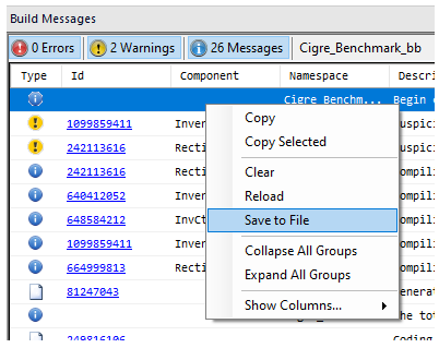
Status Bar Update: If a workspace containing multiple projects is loaded, a progress bar for the entire workspace load is now displayed in the status bar, in addition to progress bars for individual projects.
Python Scripting Improvements:
Python script record now properly records X/O marker movements.
Multiple selected components can now be identified and enumerated from a Python script.
Fixed all problems related to inconsistent font sizes in various viewing panes and miscellaneous frame sizing issues, resulting when increasing the Windows screen resolution (#7024).
Layers are now properly restored upon undo/redo actions (#8442).
Divider component parameters are now properly processed (specifically 3D/2D view), so that the appearance of the divider graphics no longer change following the parameter dialog being accessed (#8570).
When hovering over a marker label in the bottom right of a graph frame, the tooltip that appears no longer displays the title of the graph frame, but the marker's value with greater precision (#8279).
PSCAD will now handle illegal paste operations better: Either the Paste menu option will appear disabled, or a notification message will popup indicating the paste is illegal (#8623).
A blank tooltip is no longer displayed when hovering over a graph frame with no title (#8622).
The Topology Viewer no longer displays garbled, Unicode characters (#8262).
All curve properties are now properly saved upon project save (#8431).
When creating a new global substitution, the name field is automatically triggered for editing (#8630).
Current workspace name and path can now be modified via python script (#8654).
Sequence numbers no longer appear on invisible components when show sequence numbers is enabled (#8580).
Mathematical function NINT, in the component definition script, now works correctly for negative numbers (#8642).
PSCAD no longer allocates memory for disabled PGBs (#8693).
Only writable parameters are now recorded when recording a python script (#8697).
PSCAD no longer crashes if a case is run, a component is cut from the canvas, then pasted back into the exact same place, then run again (#8712).
Fixed an issue with mutually coupled line verification, where PSCAD would get stuck in an infinite loop and hang (#8729).
PSCAD V5 now supports Unicode characters in script segments, and will output to the Fortran files properly (#8724).
Blackbox now supports components possessing a MANA (Modified, Augmented Nodal Analysis) script segment (#8527).
NMANA and MBRANCHES tags are no longer written to the map file if Modified, Augmented Nodal Analysis is disabled for the project (#7961).
Element index is now properly incremented in the generated fortran code for MANA components set to 3-phase (#8761).
Accessing the Communications pane following a PNI simulation, no longer causes a crash (#8771).
Very large component script segments are now handled more efficiently, avoiding long hang periods (#8767).
If a co-simulation has been running for a long time (several minutes), it was possible for it to remain locked in a perpetual running state. This issue has been fixed (#8780).
Auto-generated Fortran code is now properly formatted in instances where there are import tags that are directly connected to export tags (#8766).
EMTDC binary output (*.psout) files may now be viewed properly as a previous run, if they were generated by a case created in PSCAD V5 (#8786).
PSCAD no longer crashes upon removal *.psout file from the resources branch when it is currently being viewed as a previous run (#8788).
Graphs are now properly populated with curves when printing (#8790).
Fixed text display issue in directly connected transmission line wires, where a line name with multiple ‘I’ characters would result in a truncated display (#8789).
Fixed a crash that could occur when using a Python copy command of a component not currently in view (#8715).
Text display settings in the script and script output panes now function properly (#8807).
Updated print interface display (#8793).
Fixed crash related to multiple modules possessing the same name (#8809).
Forcing a signal name to be the same as an auto named signal (ex. NT_1), no longer causes a signal conflict (#8758).
PSCAD V5 now properly imports v4.2.1 to v4.4 projects that contain global substitutions (#8705).
If an animated graphic is invalid, then its failure during animation will no longer cause the component to fail to draw entirely, and display unnecessary error dialog messages (#8851).
PSCAD will no longer become unstable and crash if a module definition is deleted from a library project , where an instance of that module is part of a running case project (#8852).
PSCAD will no longer crash or experience unexpected behaviour if a co-simulation component is deleted or disabled between runs (#8815).
Fixed positioning and size of switch component when viewed on a high DPI monitor (#8872).
The Python scripting library can now both read and write the table type parameter (#8875).
Graph x-axis property changes now properly stick and stay when modified manually in the respective property dialog (#8877).
Graph x-axis min and max properties are no longer force rounded according to the x-axis grid size (#8876).
The saved tracing option for simulation tasks no longer resets to its default on reload of the workspace (#8880).
When communicating with more than 5 external applications (e.g. linking a case with more than 5 or 6 PSCAD cases via alien ends transmission line interfaces), the content of the 'Inter Application Connection' dialog box now properly displays all of the information (including the case name and IP address) (#8506).
A Ctrl + Shift + Drag operation (i.e. canvas panning) now works properly and does not cause PSCAD to become unstable. Previously the operation was very slow, and could even cause crashing (#8884).
MANA branch names are now fully supported in the relevant component script segments (#8765).
The Component Parameters pane has been updated to include the new category tree format introduced with the v5.0.0 release (#8717).
Python automation no longer stalls for long periods when setting layer states in large projects (#8897).
The licencing pop-up dialog can now be silenced (as it could in PSCAD X4) by using ‘/silence:true’ (#8849).
Improvements to the FDNE Algorithm: The FDNE has been improved with more advanced curve-fitting algorithms for better accuracy (FVF, FRVF, FMVF, etc.).
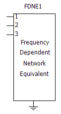
Improved parameter sanity checks in the synchronous machine component (#8587).
Fixed output file formatting of the statistical summary generated by the multiple run component (#7765).
The multi-meter component phase measurement is no longer output as 0.0, if the component is set as an ideal voltage source, whose phase is 90, 180 or 270 degrees (#8599).
Script computation NINT now works correctly for negative numbers. Both the MOD and MODULO used NINT(x) to convert a real input to integer making the results incorrect (#8643).
When the resistive_load and reactive_load are configured with zero load, the generated warning message now points to the proper component (#8670).
Enabling q-axis saturation in the synchronous machine now functions properly (#8775).
Integer ports are now properly disabled when the two-input selector component is set to complex signals (#8762).
Corrected the #STORAGE directive allocation quantities for several components (#8745).
Neither the 3-branch, Y-load nor the 3-branch, delta-load produce an error in evaluating a conditional statement (#8714).
Fixed an issue with the COMTRADE recorder component that occurs when signal variation is very small. Scaled numbers written in COMTRADE data files no longer show ****** (#8787).
The passive load model no longer slows simulation speed when RLC values change rapidly. The sensitivity to change was relaxed appropriately (#8783).
Maximum size of control signal transfer using cables has been increased from 32 to 1024. Improvements previously made to the tline interface have been incorporated into cable model, so that initial values may now be specified (#8781).
When the ambient temperature is set far below the reference cell temperature, the solar cell component no longer produces oscillatory behaviour. The sensitivity was set too high for changing conductivity. (#8698).
EMTDC no longer crashes if components exist that possess an empty MANA script segment (#8723).
The coaxial cable component no longer gives an error concerning the 1st semiconducting or insulating layer, when there is only a bare conductor present (#6380).
Fixed an error when the number of conductors equals 1, and 0 sequence data representation? parameter is not equal to Enter 0 sequence data (although disabled), in the Manual Data entry method (#6551).
Certain configurations of the YLoad component now produce matching results obtained when compared with an equivalent, detailed circuit. The neutral to ground path was acting as an open branch when shorted is selected (#8857).
Fixed the sticky limit implementation in the PI controller so that it conforms to the standard. This fix affects exciter models DC4, Ac3, AC7, AC8, AC9, AC11, ST2, ST3, ST4, ST6, ST8 and the PI controller itself (#8893).
Time domain column is now properly added on export from Advanced (*.psout) to Legacy (*.out) formatted EMTDC output files (#8741).
Fixed loss tangent calculation to use entered value in rad/s not Hz (#8751).
Increased the file path handling length to 260, which is the maximum allowed by windows (#6135).
When the ground wires are eliminated, the shunt conductance is added to eliminate the ill-conditioning of inversion of Y matrix (#5850).
When identical cables are defined in pipe model, the core type property is now properly defined for all identical cables, not just the 1st (#6755).
Results no longer differ between selecting inner cables identical, or having multiple unique inner cables that are identical in the pipe cable model (#8098).
The RXB data display is now expressed in Ohms and Siemens by default, rather than per-unit (#8881).
Now the series Z and Y is properly displayed with Manual Data Entry + external ZY. Originally Z and Y are recalculated with modified Bergeron model parameters which is not correct (#8572).
Version v5.0.0 is the initial major release of the PSCAD V5 product line. This release represents the greatest change to a single release, in terms of new features and functionalities, than any previous PSCAD version.
Intel® Visual Fortran Compiler: Versions 9.x, 10.x and 11.x are no longer supported. Support has been added for versions 16.x, 17.x, 18.x and 19.x.
GFortran 95 Compiler: Version 4.2.1 is no longer supported. Support has been added for version GFortran 8.1.
Automation: Embedded Python Scripting With Recording (#6983): Automation of the PSCAD application, utilizing custom-made Python language scripts, was first introduced in v4.6.1. It included commands to launch the software, load and run simulations, change parameters, and analyse data, among many others. Installed as standalone software, an automation controller library was bound to other Python scripting libraries, to achieve control over application-level features through an automation interface (part of PSCAD).

Non-Embedded Python Automation Interface, in PSCAD v4.6
In V5, automation utilizing the Python script language is embedded directly into the software, and is included with the installation of PSCAD.

Embedded Python Automation Interface, in PSCAD V5
Now users can maintain their scripts from within PSCAD, using a new Script pane, from which custom scripts may be recorded, edited or launched.
Script Pane
The new scripting interface comes complete with the ability to record actions – effectively writing the script for you for many of the available operations. Some manual tweaking of the file is usually required, but the bulk of it written automatically. The new interface is faster, and it alleviates the need to install Python separately (it comes ready to use with your PSCAD installation).
New Binary EMTDC Output File (*.psout) Format (#5442, #7056, #7801, #7754): With the advent of renewable energy devices, PSCAD-based studies of the effect of these devices on existing grids has become a necessity in order to ensure smooth and uninterrupted operation during and after their insertion in the network. As such, PSCAD study projects are required to represent larger and larger network models, which of course leads to greater amounts of simulated data.
The present text file based system for storing EMTDC simulation output, which has been in use for the past 20 years, was originally designed assuming much smaller simulation projects, and is therefore no longer an efficient and memory-savvy system for simulation data storage. A redesign is needed.
A brand new EMTDC output file format (*.psout) is included with the PSCAD V5 release. A proprietary design, this new format is binary, which ensures a much smaller storage footprint, as well as faster data access. Not only does it store all simulation curve and trace data, but it can also store all sequential or parallel multiple run data, as well as animated graphics information, all in a single file. For example, if you were to launch a volley of 100, parallel simulations, all EMTDC output data is stored in a single file named <project_name>.psout.

Given that binary files cannot be read using a simple text editor, a new utility, called the PSOUT Reader, is also included with PSCAD V5. This utility provides a convenient, tree-based data display environment, and includes appropriate file manipulation features, including the ability to export to the older EMTDC *.inf/*.out file format. The utility may be launched from the Tools tab of the ribbon control bar.

In addition, *.psout files from previous runs, may be added as a resource in the project it was originally run. When invoked, users can display the previously run data on the graphs within that project.
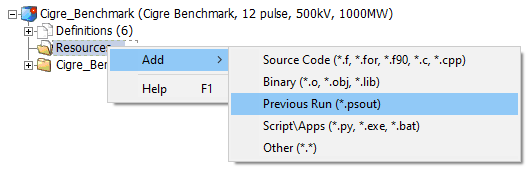
Multiple Language Support in Sticky Notes (Unicode) (#5569): The PSCAD V5 code base has been updated to fully support Unicode, which enables users to use all known writing systems within sticky notes. This of course includes the Cyrillic alphabet, Chinese characters, etc. This is a very important new feature, which has been passionately requested by many of our Asian users.
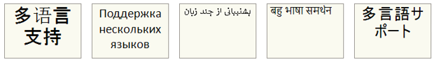
Communications Fabric (ComFab): A new inter-application communications control architecture, referred to as the Communication Fabric (or ComFab for short), is included with V5. In all prior windows versions of PSCAD going back to V3, Transmission Control Protocol/Internet Protocol (TCP/IP) had been the only protocol used by EMTDC and PSCAD to communicate during a simulation.
With the advent of high performance computing and the launching of multiple, inter-linked EMTDC simulations running in parallel, the communication overhead imposed by the TCP/IP protocol was found to be a serious speed impediment. Consequently, new means of communication were implemented to overcome this issue.
ComFab is a separate layer that acts as a middleware for communications between processes. It is generic enough to be expandable and can be utilized by third-party software to communicate with PSCAD and EMTDC, provided that protocol is adhered to. As of the V5 release, ComFab supports two types of communication interfaces: The legacy TCP/IP (default) and Shared Memory.
|
Mode |
Restrictions (Scalability) |
Performance |
Details |
|
TCP/IP |
None |
Local – 20 ms Remote – 400 ms |
This is the legacy mode of communication between PSCAD and EMTDC. Prior to PSCAD V5, this was the only mode available. |
|
Shared Memory |
Single Computer |
Local – 1-2 ms |
Shared Memory is memory that may be simultaneously accessed by multiple programs (i.e. in our case, PSCAD—EMTDC, and/or EMTDC—EMTDC) with an intent to provide communication among them. Shared Memory reduces the communication overhead to a near negligible level, but is best suited for running simulations on a single, multiple-core computer. |
Co-Simulation Interface (#4598, #6778, #7064): A general Application Programming Interface (API) is provided with PSCAD V5, enabling EMTDC to link to, and co-simulate with, just about any external application. Referred to as the Co-Simulation API, it is in it’s basic form, a C-language structure called EmtdcCosimulation_Channel, which houses a collection c-functions. These functions can be used to customize an interface on the external application-side. At the same time, a new master library component called Cosimulation, may be utilized in a case project to quickly provide the PSCAD/EMTDC side of the interface.
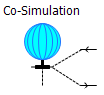
Note that the onus remains on the user to program the interface from the external application side, as all external applications differ in complexity and purpose.
Cluster Launch System (CLS): The utilization of high-performance and parallel processing functionalities requires multiple processor cores – the number of which may exceed those available locally on a typical workstation. In such situations, users may either purchase a large and expensive, high-performance computer (ex. 64-core), or connect a collection of multi-core computers across a Local Area Network (LAN). The latter option is referred to as a computational cluster.
Running processes across multiple computers requires additional software to manage the simulation processes. Enter the Cluster Launch System (CLS), a utility that can both launch and manage simulations on a computational cluster.
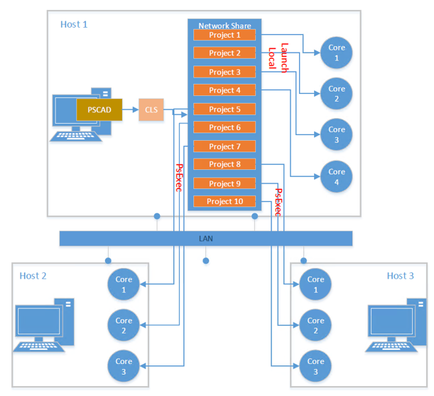
For example, a user wanting to run 10 simulations on a computer (Host 1) comprising of 4 cores, can use the CLS to configure a computational cluster and run 10 simulations using several multi-core computers connected across a LAN. As shown in the figure above, Host 1 can be treated as the master, since PSCAD is running on this computer. PSCAD launches the CLS, which is then used to configure a computational cluster comprising of Host 1, Host 2 and Host 3.
Improved Component Parameter Dialog (#7139, #7333): In an effort to provide a more efficient means of organizing very large amounts of component input and output parameter data, the component parameter dialog has been greatly improved for the V5 release. Two huge improvements were made: The manner in which parameter category pages are organized, as well as the inclusion of a Java-based, dynamic display and feedback window, called the Dynamic Help Pane.
The flat, drop-list category page format, which has been a part of PSCAD since the V2 days of the 1990s, has been replaced by a multi-level, tree-based category window. The new tree style can be extended to provide multiple branch levels (branches within branches), to provide a second dimension to the organization of categories.

New Style Category Tree
A very powerful and customizable display window, called the Dynamic Help Pane, is also included in the new parameter dialog. The new pane is simply a viewing mechanism to display the output of an associated, Java-powered, HTML file. The power and flexibility of Java and its libraries may be utilized to create a wide assortment of parameter data visualizations, from help text, to images and dynamic graphs that change as the data changes.
For example, the arrestor component in the master library has associated with it an HTML file that defines a V-I curve plot, based on the V and I parameter data entered in the dialog. The curve is displayed in the side panel window as shown below. The graph is dynamic and will change immediately if the parameter data is changed.
|
|
|
Arrestor Component in the Master Library |
Tandem Lines: Sliding Faults (#337, #2347, #7062): Tandem line configuration (or Tandem Lines) for both underground cable and overhead transmission segments is introduced with PSCAD V5. This in response to numerous requests for an easier way to automate a sliding-fault style study. The tandem lines feature combines multiple run control, parallel-processing and the transmission segment configuration components, to enable quick and efficient sliding-fault simulations.

Utilizing the basic, standalone multiple run control configured in the projects settings Runtime tab, a tandem line simulation involves a pre-solve of all possible transmission segment lengths (i.e. produces multiple *.tlo files, based on the tandem segment parameters) prior to launch. Then the simulation is run multiple times, each time using different segment lengths, creating the illusion of a sliding fault.
Mixing of Overhead and Underground Transmission Systems (#7588): The underground cable transmission segment editor and line constants program (LCP) have been modified to allow the combination of overhead transmission tower and underground cable cross-sections, within the same right-of-way.

Additional formula in the LCP takes care of the mutual impedance between aerial and underground lines.
Wire Drawing Enhancements (#2897, #1092, #7185): A couple wire-related enhancements have been included in PSCAD V5, to help alleviate some of the steps required when inter-connecting components on the schematic canvas. These new features bolster the already existing Wire Mode, which has been in use since V3:
Rubber Banding (Sticky Wires): A new, tri-segment ‘sticky’ wire component has been added to PSCAD V5. When either endpoint of this wire is attached to another object (component, bus or another wire), the wire’s endpoint will ‘stick’ to the object. If the object is moved, the wire endpoint will remain ‘stuck’, and the sticky wire will stretch (like a rubber band), as the object to which it is attached is moved around.

Wire/Bus Snap-to-Grid: A new application option has been added to provide control over how wire end-points are moved within the schematic canvas. In previous PSCAD versions, wire endpoints, when grabbed and moved, do so in a continuous motion, snapping to the drawing grid on release of the mouse pointer. The new option provides snap-to-grid functionality, while moving the wire endpoint, so that the wire position can be seen before the mouse pointer is released. The option can be found under Application Options | Environment | Schematic, and affects both wires (orthogonal and sticky), and bus components.
Wire Jumper Display Option: Wires that overlap, but are not connected will now include a visual jumper display at the overlap point. If desired, this option may be disabled in the Application Options | Environment | Schematic dialog.

COMPLEX Signal Type (#5792): Complex-type signal variables, in addition to Real, Integer and Logical-types, are now supported in PSCAD V5. Support for #LOCAL-type, complex declarations in component definition script was introduced in v4.6, but did not include the creation and support of actual complex-type data signals. V5 includes the following enhancements to provide full support:
A Complex data type option in component graphics port objects.
A Complex parameter-type for both module and non-module components.
Miscellaneous new and updated master library components, including a Complex constant tag. Also Complex signal support in many CSMF components.
New colour orange to represent Complex signal wires.
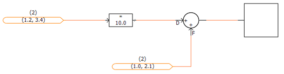
Project Navigation Enhancements (#1004, #5908, #3384): Multiple enhancements have been included with PSCAD V5, to help users navigate projects quicker and more efficiently, as well as minimizing the risk of getting lost in larger projects. Prior to V5, project navigation was performed by drilling down through multiple module layers manually. Navigating upwards was accomplished in the same way. PSCAD V3 and V4 provided a sub-tree under each project, containing a clickable representation of the existing module hierarchy, allowing users to jump to specific modules. In X4 (v4.3 to v4.6), this navigation tree was brought out into its own area, referred to as the workspace secondary window.
V5 now boasts a handful of other navigation related niceties, in addition to the navigation tree, as described in the following bullets:
Navigation Bar: Each and every schematic canvas tabbed viewing pane, possesses its own navigation bar. The bar shows the hierarchal path, including each navigation level, to the present viewing position. Each level itself is a navigable link, and displays the module definition name and instance number. Users may easily traverse up the path with a simple click of the mouse.

Bookmark Component: Bookmarks essentially special type of a component that provides a clickable hyperlink to a xy-coordinate on a specific schematic canvas within a project. Bookmarked points are first defined, and then a bookmark component can be added from the ribbon bar that, when clicked, will navigate to that exact position from anywhere in the project.
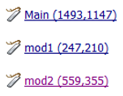
Bookmarks are also managed from within the Bookmarks pane. This pane provides a convenient and navigable list of bookmarks.

Hyperlink Component: Hyperlinks are special components that may be used to set a URL to a specific webpage, for easy access to information related to the current study, for example. Simply add a URL to the project file and give it a name.

Component Grouping (#256, #7171): The ability to combine collections of individual components into a cohesive group, is included with V5. Two or more components, once grouped, can then be moved around, copied, pasted, mirrored, flipped, rotated, or added to a layer as a single entity.

Reload Project (#4198): Case and library projects may now be reloaded in the same fashion as workspaces. Reloading a project will result in any unsaved changes being lost, however the user is warned of this before the reload commences.
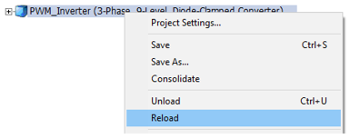
Message Log Pane (#7472): A new type of message pane is included with PSCAD V5, called the message log. This pane simply displays all messages that have been displayed to the user during the current session.

Library Project Sections in Models Tab (#6667): The Models tab in the ribbon control bar is now populated with component definitions stored in any user library project that is loaded into the current workspace. In previous versions, only component definitions from the master library would appear. Named drop list groups of definitions may be created by giving the definitions a label (edit the component definition settings). For example below, a user library project called opt_pwm is loaded into the workspace, in addition to the master library. opt_pwm contains two groups of labelled definitions called PWM and Control.

Signal Rename (#8253): It is now possible to rename a signal source and all sinks that exist on a schematic, with a single action. It is designed to provide the ability to rename all buses or components that share a name, by simply right-clicking on the bus or component, and selecting Rename….

This feature operates by detecting components with a Name parameter on the component. If a Name parameter does not exist, then the function is disabled.
New External Resource File Handling (#5383, #6704): The addition of external source (*.f, *.c) and linking of compiled object and library (*.obj, *.lib) files to a project build has, since PSCAD V3, been accomplished via two separate input fields in the project settings, or via the File Reference component. In V5, this functionality has been overhauled to organized into a convenient and intuitive, central area called the Resources Branch.

Appearing as a sub-branch of every project in the workspace projects list, the resources branch provides a means to easily manage all resource files related to a specific project. The resources branch encapsulates the functionality of both the prior project settings fields, and the file reference component, enabling users to append all types of files related to the project; such as Microsoft Word or Excel files, images, as well any type of text file, in addition to the source and linked compiled files supported in previous versions. The operating system file association settings are utilized so that the proper application is launched when the file is viewed.
Note that the File Reference component will continue to be supported in V5.
A new Application Option has also been added to the Dependencies category called Search Path, which provides a means to specify folders where the compiler should look for dependent files. In this way, only the file name need be specified in the project, as long as the file resides in one of the specified folders.
Parallel Multiple Run (PMR) (#5129, #6767): In computing, the acronym SPMD (or 'spim-D') stands for Single Program, Multiple Data, and is one of several computer architectures described in a classification called Flynn's taxonomy. It is a technique used to achieve data parallelism, where multiple instances of a simulation are run simultaneously on multiple processor cores, given different input, in order to obtain overall results quicker and more efficiently than if running them sequentially. In PSCAD, the SPMD technique is referred to more affectionately as a Parallel Multiple Run (PMR).
The PMR feature enables users to launch multiple simulation runs in parallel, based on a single case project, but providing different data to each parallel simulation task. Each simulation is run independently on its own, unique processor core.
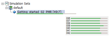
Multiple Plotted Data Sets: If the user chooses to enable tracing (passing plot data back to PSCAD for viewing) on all parallel tasks, a convenient list of data sets will appear under the simulation. These sets will represent each individual run, and when clicked, will display the data for that run in the project graphs. For example, if the tracing is enabled for all parallel tasks in the above simulation, all 49 runs will appear as follows:
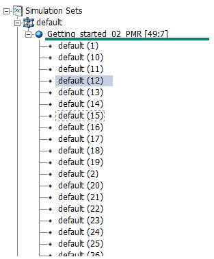
The simulation task with rank 12 is currently selected, so this data will be displayed in the project graphs.
New Global Substitutions Design (#4601, #6433): The global substitutions feature, part of the PSCAD X4 family of products (v4.3 to v4.6), has been completely redesigned for V5. Based on feedback from users over several years, we have assembled an entirely new global substitutions functionality, much more flexible and intuitive than the previous design. Major changes include:
A new global substitutions pane, which provides a central area to edit, add and delete all global substitutions related to a single project.
Inclusion of alternate global substitution values (or sets of values) when running the project as a task, in the context of one or more simulation sets.
Store, append and replace global substitutions to/from file in *.cvs format.
Set the min/max limits of slider components.

New and Improved Parameter Grid (#5609, #5976, #7410): The immensely popular parameter grid feature has been completely re-architected in PSCAD V5, specifically to address the user-identified shortcomings of its predecessor in v4.6. For the most part, the new parameter grid looks and feels like the old one. However, under the hood we have made many changes that will facilitate functionality that was missing previously. Here is a list of some the more significant enhancements:
Support for buses, transmission lines, simulation sets, file reference components and sticky notes: Virtually all schematic objects.
Results may be filtered by parameter category page, in addition to page module.
Disabled parameters (instance-based) are now displayed as such in the parameter grid results.
Store, append and replace parameter grid results to/from file in *.cvs format.
Parameter grid results may be transferred directly to a spreadsheet, modified and then transferred back via copy/paste.
Full undo/redo support.
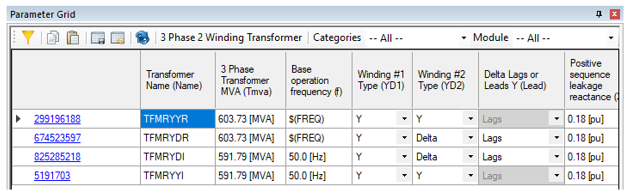
Blackbox Upgrade (#4599, #6364, #7149): The blackbox module feature, first available in PSCAD v4.5 and v4.6, has been updated in V5 to include many new enhancements, including the support of electric networks in combination with control systems.
Electric Networks Support: Starting from the top-level page module, an entire electric network, which may span across several module levels, can be collapsed into a single component, complete with multi-instance compatible, Fortran source code. The new component definition includes prefabricated graphical port arrays to represent the network, as well as pre-scripted Branch, Transformers and Matrix-Fill segments.
Global Substitutions: If project-based global substitutions are used within a module hierarchy that is to be blackboxed, the user has two options on how to process them: The default is option is to embed (hard-code) the literal value of the global substitution upon creation of the blackbox component. These values will thereafter remain constant and unchangeable. A second option allows users to make each global substitution available as a constant input parameter in the final blackbox component. Each parameter created is unique according to: 1) the actual substitution, and 2) the target unit of the parameter it is used in. For example, if a global called FREQ is used in two parameters, one whose target unit is [Hz] and the other [rad/s], two separate parameters are created.
Retention of Inner Definitions: When blackboxing a page module hierarchy (a module with other modules inside it), it is now possible to retain the blackboxed component definitions of each, individual module, as opposed to keeping just the top-level component definition. If retained, each definition is itself a blackboxed component and may be utilized exclusively from all the others.

Smart Paste (#5895, #6629, #6195, #6093, #6880, #6420): Cut/copy and paste just got a whole lot smarter in PSCAD V5. Now when an object is copied, PSCAD stores a great deal more information on the Windows clipboard, so that when it comes time to paste, an intelligent decision can be made, depending on the context of the where the object is being pasted. This can save click steps in many areas:
Copy/Paste of Output Channels: Copy an output channel component. Depending on where it is pasted, PSCAD will intelligently perform the correct operation: Paste over a graph, and a curve will be created; paste on the schematic canvas to copy the component; paste over a blank graph panel and a new graph containing a new curve will be created; paste over a control panel to create a new meter interface.
Paste External, Copied Text Directly as Sticky Note: Text copied from an external file, such as Microsoft Notepad or Word, is now formed directly as a sticky note, when pasted on the schematic canvas.
Multi-Select Copy Transfer: Select a single module or multiple modules and select copy. Paste transfer into same project or a new project.
Layer Information Included in Copy/Paste: All layer information is now included when a component is copied. On paste, the layer state will be maintained. If the layer exists already, the component is added to it; if not, a new layer is created.
Paste Rename: When a component that contains a text input parameter with symbol name Name is copied, this text can now be given a new name, based on the original seed text. For example, a component with a Name parameter with value MyComponent can be automatically renamed to MyComponent_1. This is especially useful when copying data labels, node labels and xnodes. To make use of paste rename, right-click and select Paste | Paste Rename on paste of a copied component.
High-Resolution Bitmaps: Copying of schematic canvas components now produces a high-resolution bitmap image, which when pasted into other applications, maintains a high image quality.

Enhanced Component Wizard Design (#5836): The component wizard has gone through a few changes over the years: The original design, which survived through PSCAD V3, V4 and on through to X4 (v4.3), was redesigned for the v4.4 release, and then again in v4.6. PSCAD V5 includes a completely new and refactored component wizard, our best and most powerful iteration yet. Unlike its predecessors, the V5 component wizard provides a much higher level of flexibility, including the following user-requested enhancements:
Fully sizeable box graphic.
Flexible port connection placement: Once a port is added, it can be moved around the box graphic to the desired position.
Quick access property view.
All component definition script segments may be optionally added at the time of creation.
Automatic creation of a dummy language interface to either FORTRAN, C or MATLAB, upon creation of the Fortran, Dsdyn and/or Dsout segments.

Component Graphics Editor Overhaul (#4212, #6419, #6795, #7710, #7709): The component definition graphics editor has been renewed to include functional improvements and feature enhancements.
Updated Graphics Colour Palette: The Waffleston's Revised 4-bit Color Palette, originally included with the release of PSCAD V3, and maintained throughout the V4 and X4 product lines, is updated to a full 32-bit ARGB Color Palette. This increases the number of available colours from 16 to 4,294,967,296.
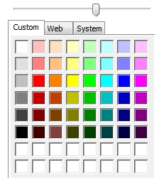
Full Font Support for Text Elements: It is now possible to adjust text elements to any font type, style and/or size (including underline and strikeout) available through the operating system. Adjusting text elements to any angle, or applying any colour (as per the updated colour palette described above) is also now possible.
New Collection of Adjustable Shapes: A new standard collection of adjustable, drawing shape elements is now available, in addition to the original line, rectangle, arc and ellipse. Each of the objects are stretchable, rotatable and come complete with a full array of adjustable properties, such as fill colours and styles (hatching and gradients).
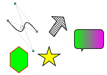
Custom Layer Configurations: Customizability has been added to the established drawing layers feature, first introduced in PSCAD v4.6.0. Custom configurations enable internal customization of a layer, by controlling the state of individual components within the layer. Users can accomplish this component state control by adding their own configurations to any layer.

Custom configuration options are stored with the project, as attributes to a particular layer, and will remain when layers are merged.
Signal Name Aliasing (#7630): Schematic canvas signals are now allowed to possess multiple names or aliases. During compilation, signals that have different names (such as a bus and an xnode that have different names, but are connected to each other) are aliased together. When compilation is complete, aliased signals are designated a single name, based on a priority system that can include alphabetical.
Aliased signal names will be displayed in flybys, and each signal variable in the generated Fortran code that has multiple aliased names, are declared on a unique line with a comment section describing the aliased names that the variable is associated with.

This added intelligence to the PSCAD schematic compiler ensures compatibility with older PSCAD projects, while providing flexibility moving forward. Signal name aliasing solves the import issue addressed by the Exported Signal Distinction application option, and so therefore this option has been removed.
Simulation Set Functionality Improvements (#5665, #6152, #6247, #6294, #7059): Simulation sets were introduced in PSCAD v4.5 in order to facilitate the launching of parallel simulations. They have been continuously enhanced in each version since, and V5 is no exception:
Project Settings Override: The ability to override runtime project settings, in each simulation task, is now included.
Layer Settings Override: If a project contains layers, individual settings may be overridden on a per-simulation task basis. This feature provides a lot of flexibility, as project schematics can be modified between simulation set runs.
Global Substitutions Set Select: In PSCAD V5, it is possible to maintain multiple sets of global substitutions for each project. A single global set may now be associated with a simulations task, allowing users to modify global substitution values between simulation set runs.
Enable/Disable Set: Use the enable/disable simulation set option to enable or disable individual simulation sets. Disabling a set will ensure it is not included when running all sets.
Parameter Grid Support: Use the parameter grid to manipulate the options of multiple simulation sets simultaneously.

Force Re-Build: The ability to force a re-build of the project, prior to launching the simulation, is now available as a Simulation Task option. When enabled, this setting will also ensure that the temporary folder is cleared between runs.
New Parallel Run Options: New options, such as Maximum Volley (limits the number parallel tasks launched on a volley), and Snapshot File (allows the selection of specific snapshot files based on rank number), have been added.
New Parameter Editor Design (#5509, #7497, #7619, #7676): The parameter editor, part of the component definition design editor, is completely refactored in PSCAD V5. The original parameter editor, included as part of the V3 and V4.1/V4.2, was updated to a brand new, windows forms-based editor for the entire X4 product series (v4.3 to v4.6).
This same editor looks similar in V5 after the update, but has been reorganized so as to display the parameter dialog dynamically, while it is being edited. This enables the user to see exactly what the dialog will look like, without the need to exit the editor, or press the Test Dialog button (the Test Dialog is still necessary for actual functionality testing, however). Also, much of the underlying functionalities have been improved and cleaned up, resulting in a more intuitive and efficient work environment.
Some other specific enhancements are described as follows:
It is now possible to control the visibility of an individual component parameter, based on a conditional statement, in addition to the existing enable/disable control. This is facilitated via a new parameter attribute called Visibility.

Quick and Easy Component Enable/Disable (#6136, #6794, #7073): Components on the schematic canvas may now have they state quickly toggled between enable and disabled, without the need to set up a layer. Note that disabling or enabling a component in this manner remains completely distinct from whatever layer (if any) the component is currently a part of. However, a disabled component will still become invisible if its current layer is set as such.

Animated Graphics Patch (#2671): The animated graphics feature has been in use since PSCAD V3, and has remained mostly unchanged since – until now. Prior to V5, the animated graphics display (ex. breaker state colour, multi-meter PQ text, etc.) would only update if the corresponding component was currently in view, during a simulation. This means that if the user was to navigate to another page module schematic after the run had finished, the graphical state of any components in that schematic may not be up to date. For example, if a breaker went from open to closed while not in view, it may still appear green if the user navigates into its page module following the end of run.
This issue has been rectified in V5, so that all animated graphics will show their last state in the simulation, regardless of whether they were viewed or not.

Status Bar Overhaul (#3008, #6671): The status bar (horizontal strip along the bottom of the application) has been rebuilt in PSCAD V5 to soften the rigidity of the previous design, which has been in use since V3. The new status bar is more flexible, and several issues regarding display text truncation and other annoyances, have been resolved. Other highlights:
User expandable display areas: Customize the status bar look and feel.
Auto-hide and reset to default buttons.

Undo/Redo Expansion (#6949, #6973): Undo/redo functionality has been expanded to additional areas of PSCAD that have not supported it in previous versions. First introduced in PSCAD V4, undo/redo has become an essential (and expected) feature in all software applications. In V5, undo/redo is now supported in the following areas, in addition to the schematic canvas:

New and Improved Macro Functionality (#2682, #6751, #6809, #6805): A handful of enhancements to how and where, both static and animated macros can be used, have been included in the PSCAD V5 release.
Sticky Notes: All static (ex. $(Compiler), $(ProjectDir), $(VersionName)), as well as animated macros (ex. %:Time, %:Month, %:Userid, %:Computer) may now be used within sticky notes. Previously these macros could only be entered as a component parameter value, for display on its graphic.
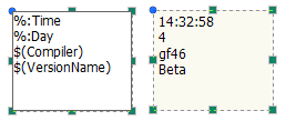
Consolidator: The consolidator was improved so that it makes use of the $(Compiler) static macro. This ensures proper folder creation to properly link compiled files when multiple compilers FORTRAN are involved.
New Static Macros: A handful of new static macros have been added to the existing list:
$(PscadPlatform) – Resolves to x86 or x64 depending on the PSCAD build.
$(EmtPlatform) – Resolves to x86 or x64 depending on the selected FORTRAN compiler.
$(MatlabPlatform) – Resolves to x86 or x64 depending on the MATLAB build being used.
Search Upgrades (#4930, #6684): The search facilities in PSCAD are constantly improving, and V5 is no exception. To the Basic Search, we have added the ability to enter direct Regular Expressions (RegEx). This enables extremely specific searches, which when dealing very large cases, can be helpful in minimizing redundant hits. Also, double-clicking on a search result will directly open the corresponding component parameter dialog, reducing the clicks required to do this in the past.

The Power of the Arrow Key (#5201, #5461, #4764): The arrow keys, which in past versions of PSCAD were used mainly for schematic scrolling, as well as miscellaneous other minor purposes, have been enhanced to include new and powerful functionalities:
Nudge: Move (or nudge) components on the schematic canvas, or graphics in the component definition graphics editor, by pressing one of the four arrow keys. Simply select the object first, and nudge away.
Traverse the Workspace Tree: While in the workspace, navigate through the tree using only the arrow keys. In addition to up and down movements, pressing the right arrow key on a collapsed branch will expand it, and pressing the left arrow on an expanded branch will collapse it.
Shift and Ctrl Hold to Select: Selecting text in script segments or elsewhere, is now enhanced to support the holding of the Shift and Ctrl keys, while moving in all four arrow key directions. Previously, text could only be selected via left mouse button hold.

Zoom Enhancements (#479, #7446): A couple enhancements have been made to the schematic canvas zooming functionality.
Custom Zoom Level: The ability to specify an exact zoom level (in 1% increments) has also been provided. Simply type in the zoom level and press enter.

Continuous Zoom: Zooming in and out of the schematic canvas in now continuous, in increments of 1%. Previously, zooming in or out (say by using the mouse wheel) would happen at pre-defined steps (i.e. 100%, 125%, 150%, etc.).

Graphing Improvements (#2154, #6500, #6226, #6148, #4786, #7281): A few improvements have been made to the graphing tools, based on customer feedback.
Graph Flyby Displays: The graphing tool data flyby viewing windows have been completely overhauled. Improvements include a table layout for clearer display of data, with display precision and column order adjustable in the Application Options. Note also, that the new flybys will no longer show off monitor, avoiding display clipping.
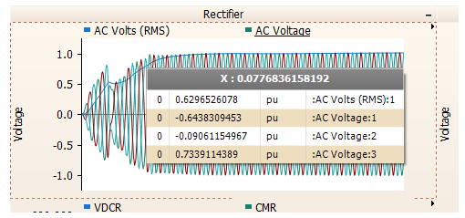
Adjustable X-Axis Labels: The x-axis labels on graphs may now be adjusted in terms of font, font size, and display angle.

Curve Colours: Curve colours are now fully customizable, based on the new 64-bit colour palette. Previously, curve colours were limited to 6 distinct colours.

The x-axis grid increment setting can now be set to manual. Previously, PSCAD would recalculate the x-axis grid automatically upon zoom. With manual zoom enabled, the x-axis grid remains static, even when zooming.
Component Scroll Using the Tab Key (#4752): It is now possible to scroll (or tab) through components on the schematic canvas, using the Tab and Shift + Tab key combinations. Simply select a component and press Tab (Shift + Tab to reverse). Tab scrolling is performed top-down, left to right.

Schematic Tab Enhancements (#6647): The schematic pane tabs have been provided with additional closing options to make tabbed pane cleanup more efficient. These include Close Tab, Close All Tabs but This, Close Tabs to the Right, Close Tabs to the Left.

Improved Ribbon File Tab (#4728): The File tab (formerly the PSCAD tab) in the ribbon control bar, has been completely redesigned to improve efficiency, and to add a bit more convenience to the user.
New Projects/Workspaces: Create new projects or workspaces by simply double-clicking the icon. Project/workspace file name and folder location may be pre-set.
Open Projects/Workspaces: PSCAD V5 maintains a list of recent case and library projects, workspaces, and recent folders visited. Find your files at lightening speed.
Workspace Tree Multi-Select (#2837, #4224, #5874): Relevant branches of the workspace tree, have been enhanced to allow for the selection of multiple items, to enable compound operations.
Definitions Branch: In the Definitions branch under each project, multiple definitions may be selected and then deleted or copied simultaneously.

Simulation Sets: Multiple simulation sets may be selected at once, allowing limited, compound operations.
Simulation Tasks: Compound operations may now be performed on multiple simulation tasks at once. This includes options and overrides.
Table Parameter Improvements (#6762, #5271): The usability and display of table-type parameters, first introduced in PSCAD v4.3.1, has been greatly improved in V5. When invoked, table parameters are now displayed in a separate pop-up dialog, which allows copy/paste of data, is resizable, and is generally easier to use with less pitfalls than the previous design.

Output Channel Limit Increased (#6267, #6905): The hard maximum limit for output channels per simulation has been increased from 2,048 to 65,536 in the professional edition only. The prior limit had been imposed, due to the fact that the PSCAD-EMTDC message buffer would become overrun (when more than 2000 output channels existed), resulting in message blocking and other annoyances. The PSCAD-EMTDC communication mechanisms have been enhanced in V5 to allow for increased message traffic, without overrunning the buffer.

#COMPONENTID Script Directive (#4223): A new directive was added to the PSCAD Script, called #COMPONENTID. When this directive is encountered during processing, it is replaced directly with the following in the corresponding FORTRAN (*.f) file.
CALL COMPONENT_ID(ICALL_NO,<component_id>)
The use of the #COMPONENTID macro is recommended when building custom components, as it reduces the chance of typos, plus will ensure custom component script remains compatible in future versions.
$#Type Script Directive (#6417): A new directive was added to the PSCAD Script, called $#Type(n). This directive can be used in logical statements when checking for the type (i.e. Electrical = 0, LOGICAL = 1, INTEGER = 2, REAL = 3 or COMPLEX = 4) of a port, parameter or computation variable. For example:
#IF $#Type(input)==2
In the above statement, the signal type of a port called input, is checked if it is of INTEGER-type (INTEGER = 2).
Component Parameter Condition Mode (#7094): A new control attribute has been added to all component definition parameter types, called Condition Mode. Condition Mode may be set to Enabled or Visible, where Visible is the new functionality. When set to Visible, parameters will become invisible if the corresponding conditional statement in the Condition attribute is false, as opposed to simply being greyed-out if Enabled is selected (legacy).
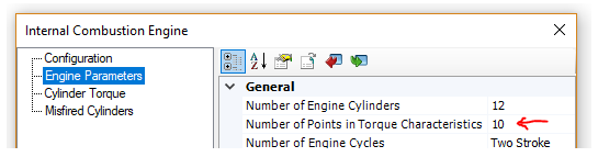
|
|
|
|
Condition Mode Set To Enabled |
Condition Mode Set To Visible |
(Since v4.6.3)
The bolded (modified) state of parameter input field values is now reverted back to un-bolded, if the user reverts it back to its initial state (#6299).
The project compiler now checks for port dimension validity and posts an appropriate error if found (#6379).
If more than approximately 150 projects are loaded into a single workspace, and each is opened, PSCAD would crash. This has been fixed, by not allowing more than 32, simultaneously opened project schematic panes (#6435).
Modules possessing output parameters that are disabled, due to a conditional expression, are now properly dealt with. Previously a runtime error would occur with no valid messages (#6616).
It is no longer possible to copy a definition from the workspace tree and paste it onto the schematic canvas. Previously, doing this would add invalid (but harmless) XML elements to the project file (#6229).
The conversion of the letter ‘C’ or ‘c’ in the first column of component script, is no longer presumed to be a comment and replaced with an explanation point ‘!’. This was an older FORTRAN 77 to 90 conversion, which is no longer necessary (#6750).
Global substitutions may now be used to set parameter values in online controls components (i.e. sliders and switches) (#6652).
The proper plotting context is now displayed when output channels, defined within a page module whose definition is stored within a library project, is instantiated in multiple different case projects, and each project is run separately. Previously in this situation, only curve data from the last project in the data stack was displayed in all projects (#5807).
A padding margin of 0.25% is automatically applied to all graphs when zoom extents is used. This ensures that constant data close to the y-axis boundary is clearly displayed in the graph (#6846).
Conditional statements used for category pages or individual parameters, will now default to false if the statement is invalid for any reason. Previously they would default to true (#6827).
Node search is now set to global node number by default (#6856).
Clicking refresh on the models tab of the ribbon control bar, no longer renders the tab unresponsive (#6633).
Sequence order numbers are no longer displayed on data labels, xnodes and node labels. These components are not part of sequence ordering and display on them clutters the schematic (#6606).
Fixed a crash point that could occur if a user manually adds transmission segment instances to a project, by manually editing the XML, and not including an accompanying definition (#6958).
It is no longer possible to select a component, that resides under a graph pane, while performing graph related operations within that pane. An issue was fixed with the drawing layer ordering mechanism, which also fixed an issue the comparator tool display results (#6960/#6957).
The divider component now works properly in 2D mode. Previously, changes to parameters did not stick when the OK button was pressed (#6959).
Fixed a crash point involving a certain sequence of navigation steps. This was caused by PSCAD attempting to access invalid cached information (#6963).
Speed performance has been greatly enhanced in situations when performing PNI or PMR simulations, where the number of parallel simulations exceed to number of processor cores available (core overloading). There is still a speed performance hit in these situations; however, it is vastly improved over previous versions, where the simulation speed was decreased to almost a standstill. Ensuring there are more cores available than simulations is still a recommended practise (#6898).
Manually modified graph settings no longer revert to their previous state, upon resize of the schematic canvas, following the modifications (#6966).
EMTDC simulations are now prevented from running if the number of time steps exceeds 231. Anything higher than this exceeds the maximum allowable value for an integer (#6556).
A search is now performed, if the 'Filter Search' box is enabled, but no filter is selected. Previously no search was performed under this condition (#6975).
Copy as metafile and copy as bitmap are now free of dysfunction, and have been added to the smart paste feature. Simply select, copy and paste in any external application (#5951, #6228).
Case projects no longer get flagged as modified by simply running them (#6941).
PSCAD now provides options in the event that the user tries to re-run an EMTDC process that was not properly shut down (possibly due to a PSCAD crash). Previously there was no indication of such ‘orphaned’ processes, leading to confusion (#7034).
Issues with incorrect component text justification, following a mirror action, have been corrected (#7010).
The nodal matrix display now functions properly when viewing smaller systems, where optimal node ordering is not performed (#7077).
A new application option has been added to allow users to control the status of the Store feed-forward signals for viewing project setting, while blackboxing. Previously, and still by default, blackbox forces this setting false, in order to optimize the generated source code. However in some instances, when custom models exist that contain improper storage read/write statements, forcing this project setting disabled would result in different simulated results after the blackbox component was substituted for the original module (#7093).
The graph frame vertical scroll bar is no longer visible, when the graph is copied/pasted outside the application, while in plain paper mode (#4550).
The send-to-back and bring-to-front functions now work properly for schematic objects like components and sticky notes (#7109).
PMR-I (root control) will now launch if the number of slave projects in the workspace exceeds the number of receiving transmitters on any slave (#7160).
Graphs no longer draw curves (bleed through) when underneath other components or other graphs (#6249).
The size limit for both a single line of text in a component definition script segment, as well as the entire script segment, has been removed (#7161).
Dynamic zoom (Ctrl + mouse wheel) now centres properly on the mouse pointer, allowing a directed dynamic zoom (#4444).
Dynamic zoom (Ctrl + mouse wheel) now centres properly on selected components when component are selected (otherwise centres on the mouse pointer) (#7206).
PSCAD now properly manages simulation data that is sourced from a module (online controls and output channels), whose definition is stored in a library project, and instances of that module exist in parallel tasks. Previously in situations where there are two or more tasks in a simulation set, and each task project contains a reference to the same module hierarchy, which is stored in a library project, jumbled results no longer occur (#6260).
Users are no longer forced to verify saving every project, on selection of ‘Save All Projects’ from the workspace Projects branch menu (#6894).
The destination schematic canvas is now properly resized when pasting a group of components copied from a larger canvas (#7364).
Marker grips and lines no longer become unsynchronized when moving markers via the arrow keys (#7290).
Subroutine calls in Fortran containing large numbers of arguments (longer that 2048 characters in a single line of script) no longer causes a crash (#7488).
Static library (*.lib) files now link properly on build, when a case project contains more than 10 modules (#7577).
Newly added wire vertices now immediately appear when using the 'v' hotkey or the context menu item insert wire vertex (#6579).
Creating a new workspace, or loading or reloading an existing one will now reload the master library project, if it has been modified (#4768).
Both simulation sets and simulation tasks may now be manually ordered within the Simulations tree (#4758).
Mutual coupling distance to reference t-line/cable input parameter presumed is no longer presumed as kilometres, if entered as unit-less (ie. 60.0 no longer converts to 60,000 m) (#7541).
Plain paper mode for graph and control panels now displays properly. Previously, buttons were drawn with a black background when the environment was set to best quality graphics (#7135).
PSCAD no longer crashes when obscure, invalid characters are used in the project namespace name, such as ‘. This could occur when a project file is manually edited in a text editor (#7607).
Blackbox no longer assumes the centre point of the component graphic (i.e. 0,0) as its starting point for electrical port placement. It now starts from the centre of the component graphic extents (#7648).
Copying of data from graphs no longer adds an extra column of data when Copy Data to Clipboard | All is selected. Also, no data is copied via Copy Data to Clipboard | Between Markers, if the X and O markers are atop each other (#6933).
PSCAD now sanity checks the Transformers script segment during compilation. Checks are made to determine if the number of transformer data sets equal the number of transformers indicated (#TRANSFORMERS), and if the maximum number of lines in all sets does not exceed the indicated maximum number of windings (#WINDINGS) (#7673).
PSCAD now prompts the user by default if legacy issues are detected on import of older cases, prior to actually modifying the project (#7054).
The signal from the receiving end of the control signal carrier may now be manually set for the first time step of simulation. Previously this number was always 0.0, without the ability to control its value (#7705).
EMTDC now displays the offending filename when issuing a runtime message sourced from OPENFILE1 (#7573).
Port IP address binding is no longer an issue when multiple network adapter cards are installed on the same local host machine (#7819).
PSCAD no longer fails to build if any other debug warnings are enabled, in addition to the argument mismatch debug warning (#7831).
Curves may now be added to XY Plots via drag and drop (either move or copy) (#7842).
The ability to directly copy graph panels by ID number (using python script) has been added (#6699).
PSCAD now displays the current product version in the project build messages pane (#7950).
Parameters of components residing within the transmission segment definition canvas, may now be modified using Python script automation (#6338).
Scenarios associated with controls that are part of a non-instantiated module, may now be managed via the scenario viewer (#7958).
Invalid namespace names are no longer accepted for library projects. Names must conform to Fortran naming conventions (#7907).
Electrical ports identified as internal, can no longer be connected via a wire, or any other means (#1105).
Flybys that result when hovering the mouse pointer over a component port, now properly display the port name and description (if it exists) (#7422).
Curve legends flybys now display a full path to their respective source modules (#8119).
When pasting components using the right-click context menu, the component is now pasted where the right-click occurred, not at the current mouse pointer position (#8387).
Support has been added to ensure proper type-casting on import/export signals on module components (#8418).
Blackbox now chops call statements to a reasonable length, using the inherent ‘+’ operator in the component definition script (#6337).
Polygraphs containing multiple curves no longer misalign with labels if some traces are hidden (#8419).
MMC Full-Bridge Cell: This component models a multi-valve, full-bridge MMC with Thévenin equivalent circuits, which effectively increases the computational efficiency.
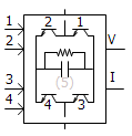
MMC Half-Bridge Cell: This component models a multi-valve, half-bridge MMC with Thévenin equivalent circuits, which effectively increases the computational efficiency.

Firing Signal Generator for MMC Full-Bridge: This component generates firing signals for full-bridge cells, based on the capacitor voltage balancing algorithm.

Firing Signal Generator for MMC Half-Bridge: This component generates firing signals for half-bridge cells, based on the capacitor voltage balancing algorithm.

MMC Multi-Dimensional Comparator: This component compares modulating waves against carrier waves generated by MMC Carrier Signal Generator, and outputs control signals to MMC cells.
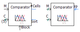
MMC Carrier Signal Generator: This component generates a vector of PWM carrier signals for a specified fundamental frequency.

1-Phase Induction Machine: This component models a single-phase induction motor.

Z-Domain (Discretized) Controls: A library of eight, commonly used controls components have are included in the master library. These include: Delay, Derivative, Differential Pole, Integrator, Lead-Lag Pole, Transfer Function, PI Controller and Real Pole.

1-Phase, Multi-Winding (5-12), Transformer: This component models a single-phase, ideal transformer that can be configured to model from five to 12 windings. Options are provided to enable a simple saturation model on a user selected winding, as well as for adding a tap changer.

3/5-Limb, Duality-Based Transformer: This component represents a mode of a 3-phase, 2-winding transformer, based on the principle of duality.

Hysteresis Reactor: This component models a hysteresis reactor. It can be connected to a single-phase or 3-phase node.

3-Phase Current Source: This component models a 3-phase, positive-sequence, ideal AC current source.

Current Dependent Current Source: This component models a single phase or three-phase scalable current dependent current source.

Voltage Dependent Current Source: This component models a single phase or three-phase scalable voltage dependent current source.

Voltage Dependent Voltage Source: This component models a single phase or three-phase scalable voltage dependent voltage source.

Ideal Ratio Changer: This component models a single phase or three-phase scalable ideal ratio changer (i.e. a combination of voltage dependent voltage source and a current dependent current source).

IEEE Standard 421.5-2016 AC Exciters: The collection of AC Exciters in the master library have been updated from the previous 1992, to the revised 2016 IEEE standard. Includes AC1C, AC2C, AC3C, AC4C, AC5C, AC6C, AC7C, AC8C, AC9C, AC10C and AC11C models.
IEEE Standard 421.5-2016 DC Exciters: The collection of DC Exciters in the master library have been updated from the previous 1992, to the revised 2016 IEEE standard. Includes DC1C, DC2C, DC3A and DC4C models.
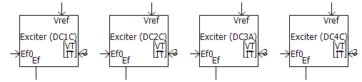
IEEE Standard 421.5-2016 Static Exciters: The collection of Static Exciters in the master library have been updated from the previous 1992, to the revised 2016 IEEE standard. Includes ST1C, ST2C, ST3C, ST4C, ST5C, ST6C, ST7C, ST8C, ST9C and ST10C models.

Individually Configurable, Delta-Connected Load: This component models a delta-connected load. Each branch can be individually selected to be any series combination of R, L and C elements, or as an open branch.
Individually Configurable, Delta-Connected, 3-Branch Load: This component models a delta-connected load. Each leg is a combination of two, parallel branches in series with another branch. Each branch can be individually selected to be any series combination of R, L and C elements, or as an open or shorted branch.

Individually Configurable, Y-Connected Load: This component models a Y-connected load. Each branch can be individually selected to be any series combination of R, L and C elements, or as an open or shorted branch.

Individually Configurable, Y-Connected, 3-Branch Load: This component models a Y-connected load with a neutral connection. Each leg is a combination of two, parallel branches in series with another branch. Each branch can be individually selected to be any series combination of R, L and C elements, or as an open or shorted branch.

Per-Unit Impedance Branch: This component models a 3-phase passive branch of R, L and C elements. Parameters are entered as per-unit impedances, based on specified base values.

Isolation Switch: This component models an isolation switch for electric circuits. The status of the switch can not be changed during the run. The switch is modelled as an infinite or zero impedance branch.

TRV Envelope Generator: This component generates standardized Transient Recovery Voltage (TRV) curves and outputs violations when the input voltage exceeds the envelope. This is a simplified approach to determining whether a breaker will restrike after a current interruption.

Harmonic Signal Generator: This component generates a signal composed of user-defined harmonics of varying magnitudes and phases. Harmonic numbers and associated peak magnitudes and phases can be input through ports as an array signal. Alternatively, the user can specify them from a file.

Pick-Up, Drop-Out Timer: This component models a pick-up, drop-out timer.

Clark/Inverse Clark Transform: This component performs Clarke or Inverse Clarke transformation.
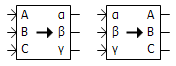
Change Detector: This component detects changes in the input. The output is 1 if a change is detected, otherwise it is 0.
Dead-Band Controller: This component models a dead-band controller.

Scale Changer: This component does a linear transformation of the input signal in y = mx + c form.

Discretizer: This component discretizes the input signal, from a specified range to a different discretized range.

Sort Indexer: This component examines an input data array and outputs the sorted indices of the array in ascending or descending order.

Complex Conjugate: This component outputs a complex conjugate signal, based on the input, complex signal.

Electrical Phase Tap: This component may be used to tap off a single phase, from a multi-phase electrical wire.

Backlash: This component models a backlash controller.

Complex Constant: This component is used to create a constant, COMPLEX data signal.

Modified, Augmented Nodal Analysis (MANA) (#6604, #7085, #7086, #7671): Pending.
PSCAD Interface to EMTDC: PSCAD interfaces MANA data to EMTDC via the project Map and Data files. MANA data is entered individually in each component definition, using a new script segment called MANA.
kLDU: Pending.
Mutually Coupled Three Wires (#8233): The Mutually Coupled Three Wires component has been updated to provide the ability to model a zero-impedance transmission line. This is helpful when importing models from powerflow software.
Complex Signal Support (#5792): Most of the standard controls components (CSMF) have been updated to support the new complex signal type in PSCAD V5.

Array Signal Support (#4022): Most of the standard controls components (CSMF) have been updated to support array signal (vector) input and output. All components are by default scalar. To utilize array signal functionality, simply modify the component dimension parameter.
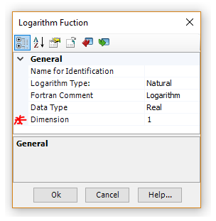
Multiple Run Additional Recording Statistical Summary: The ability to add a statistical summary to the output file has been added to the Multiple Run Additional Recording component.

FFT Enhancements: The Fast Fourier transform component now provides support for output signals up 1023 harmonics. A new input parameter has been added to allow enable/disable control of frequency tracking using a signal variable.
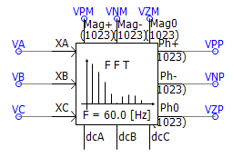
B-H Core Characteristic for Saturable Reactor (#3418): The Saturable reactor core characteristic can now be represented as a B-H curve, where data is entered Flux Density (T) vs. MMF (A/m).

Permanent Magnet Machine Neutral Connection: The Permanent Magnet (PM) machine component has been provided with an external connection to the neutral point of the stator windings.

(Since v4.6.3)
The saturable reactor now removes the 1st point, rather than the 2nd point, when it encounters to successive, identical slopes in the piecewise linear saturation curve (#6885).
The conductor dc resistance input parameter in the transmission line towers has been changed to clearly state what values are expected (#6862).
A bug in the logarithm function script, which resulted malformed FORTRAN, has been fixed (#7048).
An RLC input data option has been added to the -section component (#6970).
Differential, lead-lag and real pole components now accept negative gain input, with limits enabled (#7026).
Real pole component min/max limits are no longer used in the code, even when the limits are disabled (#7143).
In the photovoltaic (PV) source, a numerical overflow situation is now avoided by limiting the voltage when taking the exponential.
DC Machine: A potential situation to modify input parameters was avoided by copying the parameters to a different variable.
An accurate amount of reactive power is now drawn, when hysteresis (both basic and JA) is enabled on a 4-winding transformer, during an open circuit test. Previously a glitch in the component parameters set the number of winding to 3 instead of 4 (#7625).
The DC2A exciter component now properly enables the under excitation limit (UEL) input parameter when configured as such (#7626).
In a volley launch situation, the seed for random number generation is now unique (#7029).
Transformer tap changer was not working correctly in some specific situations (#7092).
Output of yoke flux in single-phase 3/4 winding transformer is no longer always zero (#7119).
Phase angle of FFT no longer oscillates between -90 and 270 instead of -180 and 180 when configured for Sequence/Sine/Degrees (#7238).
Basic hysteresis model was not working correctly with some compilers when the transformer is energized later than time = 0 (#7274).
1The harmonic interface solution no longer gives incorrect values in open-circuit situations involving non-resister/inductor or capacitor branches (#7237).
In a classical 3-Phase 2-Winding transformer model, when a delta winding is present and Lead is selected, internal outputs of fluxes and magnetizing currents are no longer out of phase (#7581).
The yoke flux output in 3/4 winding UMEC single-phase transformer, is no longer output as 0.0 (#7119).
The GFortran compiler flags have been be revised for optimum run speed (#7452).
The calculated copper losses in the 2-winding auto-transformer have been corrected (#7987).
The modulator master library component now uses proper storage syntax (STOR change to REAL) (#8077).
Fixed errors n ST5B and ST7B exciter models (#8158).
The COMTRADE recorder now properly captures the trigger time (#8124).
Fixed a minor definition script formatting error in Inverse Time Over Current [51] Element component (#8187).
Arrestor: Fixed a problem with storage allocation being insufficient when used with an external data file (#8255).
Passivity enforcement of transmission lines and cables, based on constrained optimization via spectral residue perturbation of propagation function, has been implemented.
It is now possible to model overhead towers and cables (aerial or underground) in the same cable model, with mutual coupling between them.
Extended earth return formula for aerial cables (calculates via efficient quadratic integration algorithm – Ametani/Liu). The aim is improved accuracy for GIS studies (frequencies up to 10 or 100 MHz, whereas the older formula is accurate up to only 1 MHz). More importantly this improves numerical stability of short, aerial GIS pipes. This algorithm calculates frequency-dependent ground impedance, as well as ground admittance.
Extended earth return formula for underground cables (Ametani). This improves the accuracy and stability of short cables. This algorithm calculates frequency-dependent ground impedance, as well as ground admittance.
Accurate cable insulation loss representation, using loss factor for cables (including pipe-type cables), where the loss is modeled as a property of the insulation material. The cable shunt conductance is now obsolete (shunt conductance is also not valid in pipe-type cables, due to the shape of the inner insulation). In earlier versions, there was an ill-condition in calculating parameters at very low frequencies in the absence of insulation resistance. Hence, the DC Correction algorithm could not be applied to pipe-type cables.
Cable algorithm now can handle large cable systems of more than 12 cables in parallel.
Fixed a problem with DC Correction when the first entry of fitted propagation function is a complex pole.
Fixed a problem in the pipe-type cable when calculating the pipe mutual impedance. A coding error in evaluating equations containing Bessel functions is fixed.