The COMTRADE Recorder component can record up to a total of 28 simulated data signals. The recorded data is stored in standard COMTRADE 99 format.
External Recording Channels:
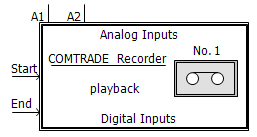
A1, A2,...,A12: Analog input channels
D1, D2,...,D16: Digital input channels
Recording Control:
Start: Adjustable recording start time [s].
End: Adjustable recording end time [s].
Start and End inputs are provided for control of a specified recording interval. Normally, a simple constant value may be attached to these inputs, however more complicated systems may be used to vary these times during a multiple run simulation.
|
More: |
Main ConfigurationMain Configuration
|
Name for Identification |
Text |
Optional name for identification of the component. |
||
|
Output File Name |
|
Text |
|
Enter the output file name with no extension. The length of the file name is limited to 8 characters for COMTRADE compatibility. Appropriate extension(s) will be automatically appended. |
|
|
|
|
|
|
|
Recording Time Step (microseconds) |
|
INTEGER |
Literal |
Enter the recording time step. If this value is less than the simulation time step, the simulation time step will be used instead. If the recording time step is greater than the simulation time step, interpolation is used for synchronization between the two [ms]. |
|
|
|
|
|
|
|
Low Pass Filtering Enable |
|
Choice |
|
Select Rstep > Tstep to enable low pass filtering of input signals when Recording Time Step is greater than the simulation time step. |
|
|
|
|
|
|
|
System Frequency |
|
Choice |
|
The fundamental system frequency. Select 50 Hz or 60 Hz. |
|
|
|
|
|
|
|
Station Name |
|
Text |
|
Enter a descriptive station name. |
|
|
|
|
|
|
|
Recorder Device Number |
|
INTEGER |
Literal |
Enter a number from 1 to 99. This parameter allows EMTDC to distinguish between multiple recorders used in the same simulation. If this is the case, then each recorder must be assigned a unique device number |
|
|
|
|
|
|
|
Number of 16-bit Analog Channels |
|
INTEGER |
Literal |
Enter the number of 'analog' input channels to be recorded (12 maximum). |
|
|
|
|
|
|
|
Number of Digital Channels |
|
INTEGER |
Literal |
Enter the number of 'digital' input channels to be recorded (16 maximum). |
|
|
|
|
|
|
|
Output files |
|
Choice |
|
Select Single or Multiple. The COMTRADE specification permits large output files to be split into smaller files suitable for transfer between computers via 1.44MB floppy disks |
|
|
|
|
|
|
|
Number of Extra Header File Lines |
|
INTEGER |
Literal |
Select the number of lines to be added to the COMTRADE header file (5 maximum). The text is entered via the Header File category page. |
|
|
|
|
|
|
|
Analog Output Minimum |
|
INTEGER |
Literal |
For uni-polar integer representation of the captured data, enter 0. For bipolar representation, enter the appropriate value (ex. -4096). |
|
|
|
|
|
|
|
Analog Output Maximum |
|
INTEGER |
Literal |
For uni-polar integer representation of the captured data, enter the appropriate non-zero value. |
|
|
|
|
|
|
|
Capture Trigger Time |
|
Choice |
|
Select Yes or No. |
|
Extra Header File Line # |
|
Text |
|
The user can enter descriptive text desired in these lines. This parameter is used only if Number of Extra Header File Lines is non-zero |
Analog Channel A#Analog Channel A#
|
Analog Variable Name |
|
Text |
|
Enter the 'analog' input variable name. It should be less than 15 characters in length with no spaces between characters. |
|
|
|
|
|
|
|
Variable Description |
|
Text |
|
Enter the variable description to be used in the COMTRADE configuration file. |
|
|
|
|
|
|
|
Variable Source |
|
Choice |
|
Select Primary or Secondary source. This parameter accounts for the CT/PT ratio. If Secondary is selected, then the value at the recorder input is passed directly to the output file. If Primary is selected, then the value at the recorder input is divided by the CT/PT ratio. The value sent to the recorder output file is always the secondary level |
|
|
|
|
|
|
|
Variable Type |
|
Choice |
|
Select Voltage, Current or Other. This information is required by COMTRADE files to display the proper units. If Other is selected then ASCII text can be added to describe the units for Other, and no scaling occurs. |
|
|
|
|
|
|
|
"Other" Unit |
|
Text |
|
The user can enter whatever units are appropriate for the enabled channels |
|
|
|
|
|
|
|
Phase Identification |
|
Choice |
|
Select phases A, B, C, or N. |
|
|
|
|
|
|
|
PT or CT Ratio |
|
REAL |
Literal |
Enter the PT or CT ratio for each variable. Remember that in PSCAD, the default primary values are in kV or kA. |
|
|
|
|
|
|
|
Component Being Monitored (COMTRADE) |
|
Text |
|
Describe the component that is being monitored as required by the COMTRADE configuration file. |
Digital ChannelsDigital Channels
|
Status Variable Name |
|
Text |
|
Enter the 'digital' input variable name. It should be less than 15 characters in length with no spaces between characters. |
|
|
|
|
|
|
|
Variable Description |
|
Text |
|
Enter the variable description to be used in the COMTRADE configuration file. |
|
|
|
|
|
|
|
Normal Operating State |
|
Choice |
|
Select 0 or 1. This information is required by the COMTRADE configuration file and is used to assign a default initial value to digital signals. |