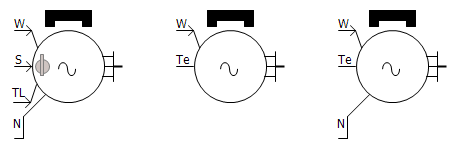
This component models a permanent magnet synchronous machine. In addition to the three stator windings, two additional, short-circuited windings are included to model the effect of electromagnetic damping. The speed of the machine may be controlled directly by inputting a positive value into the W input of the machine, and Te is the output electrical torque.
The following equations describe the model:
|
|
|
|
|
Voltage Equations for the Main Stator Windings in the dq0 Reference Frame |
Voltage Equations for the Short-Circuited Windings in the dq0 Reference Frame |
Flux Linkage Equations of the Windings |
Where,
|
|
Flux linkage of the shorted damper windings |
Multi-mass Disabled:
W: Speed input in per-unit. The machine runs at this speed while in speed control mode.
S: Switch to select speed control mode (1) or torque control mode (0).
TL: Torque input in per-unit. If the machine is in torque control mode then the machine computes the speed based on the inertia and damping coefficient, this input torque and the output torque.
Multi-mass Enabled:
W: Speed input in per-unit. The machine runs at this speed, which is specified by the multi-mass interface.
Te: Per-unit Electrical torque output of the machine. This torque is passed to the multi-mass interface, which computes the speed based on this torque, mechanical torque (TL) and parameters within the multi-mass component.
|
More: |
NOTE: These parameters are used to calculate the base values for machine speed and torque.
|
Name for Identification |
|
Text |
Constant |
Identifying name. |
|
|
|
|
|
|
|
Data Format |
|
Choice |
|
Select Equivalent Circuit or Dynamic Model.
Equivalent Circuit data format represents the electrical characteristics of the machine using parameters like resistance (R) and reactance (X). Dynamic Model data format describes the time-varying behavior of the machine, including key aspects such as transient time constants and transient reactance. |
|
|
|
|
|
|
|
Multimass Interface |
|
Choice |
|
Select Enable or Disable. See Interfacing to the Multi-Mass Torsional Shaft for more details. |
|
|
|
|
|
|
|
External Connection to Neutral |
|
Choice |
|
Select Enable or Disable. Selecting Enable will give external access to the neutral point of the stator windings. |
|
|
|
|
|
|
|
Rated MVA |
|
REAL |
Constant |
Rated MVA of the machine [MVA] |
|
|
|
|
|
|
|
Rated Voltage (L-L) |
|
REAL |
Constant |
The rated line-to-line voltage of the machine [kV] |
|
|
|
|
|
|
|
Rated Frequency |
|
REAL |
Constant |
Rated electrical frequency of the machine [Hz] |
|
Magnetic Strength |
|
REAL |
Constant |
The flux linkage due to the permanent magnet. The SI unit for this parameter is kWb-turns. The per-unit value is such that 1 pu magnetic strength will produce the rated terminal voltage when the machine is rotating at the rated speed and at no load [pu]. |
|
|
|
|
|
|
|
Stator Winding Resistance |
|
REAL |
Constant |
Stator winding resistance [pu] |
|
|
|
|
|
|
|
Stator Leakage Reactance |
|
REAL |
Constant |
Stator winding leakage reactance [pu] |
|
|
|
|
|
|
|
D: Unsaturated Reactance [Xd] |
|
REAL |
Constant |
Direct-axis reactance [pu] |
|
|
|
|
|
|
|
Q: Unsaturated Reactance [Xq] |
|
REAL |
Constant |
Quadrature-axis reactance [pu] |
|
|
|
|
|
|
|
D: Damper Winding Resistance [Rkd] |
|
REAL |
Constant |
Direct-axis damper winding resistance [pu] |
|
|
|
|
|
|
|
D: Damper Winding Reactance [Xkd] |
|
REAL |
Constant |
Direct-axis damper winding reactance [pu] |
|
|
|
|
|
|
|
Q: Damper Winding Resistance [Rkq] |
|
REAL |
Constant |
Quadrature-axis damper winding resistance [pu] |
|
|
|
|
|
|
|
Q: Damper Winding Reactance [Xkq] |
|
REAL |
Constant |
Quadrature-axis damper winding reactance [pu] |
|
Angular Moment of Inertia (J=2H) |
REAL |
Constant |
This is the total inertia of all masses rotating on the machine shaft (including mechanical loads). If you are provided with the value of the Inertia Constant (H), multiply the value by 2 to obtain the value of J in per unit. [s] or [MWs/MVA]. |
|
|
Mechanical Damping |
REAL |
Constant |
Enter a value for mechanical damping to compensate for friction and windage loss [pu] |
Internal OutputsInternal Outputs
|
Rotor Position |
|
Text |
|
Position of the rotor d-axis with respect to the magnetic axis of the Phase A winding [rad] |
|
|
|
|
|
|
|
Mechanical Speed |
|
Text |
|
Mechanical speed [pu] |
|
|
|
|
|
|
|
Electrical Torque |
|
Text |
|
Electrical torque [pu] |