Right-click on a blank part of the schematic canvas and select Canvas Settings... These settings are specific to a single module definition, and will affect all instances of that module.
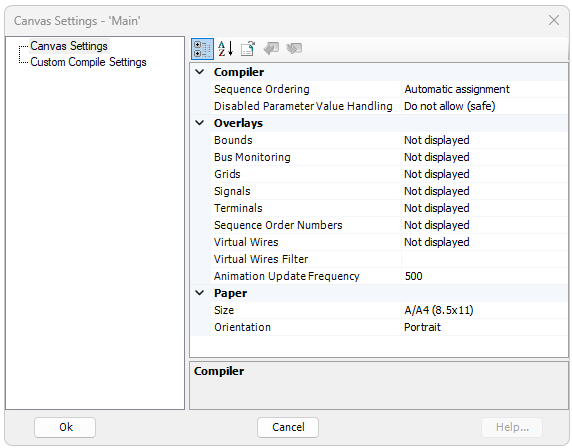
A dialog window entitled Canvas Settings will open by default, as shown below:
The Canvas Settings dialog inputs are described in the following sections.
These options are related to the way in which system dynamics code is ordered. For more on this option, see Component Ordering.
Sequence Ordering: Enable this option to ensure that a PSCAD smart algorithm will automatically order your control components. This algorithm systematically scans all control systems and sub-modules within the module and determines the sequence in which each component should appear in the in EMTDC system dynamics. This option is by default enabled, and should remain that way unless the user wants to reorder these components manually.
Disabled Parameter Value Handling: If this module possesses disabled parameters, use this option to manage them. The ability to disable module parameters was a loophole in PSCAD versions up to and including v5.0.2. As of v5.1.0, this is no longer allowed. However, we have provided the ability to manage them on an individual module basis, in order to support legacy projects that have them. See What's New? for more details on this.
These options are related to the page display.
Bounds: Set this option to show resizing bounds to display one paper size smaller than the current size. This is especially convenient when attempting to reduce the page size of a canvas containing components and other objects.
Bus Monitoring: Set this option to view voltages on all buses.
Grids: Set this option to view the major grid points on the module page.
Signals: When this option set, PSCAD will use icons placed on data signal wires and connections, so as to allow for easy, graphical differentiation between feed-forward and feedback signals. A 3rd option is also given to diplay only feedback type signals. See Show Signal Locations for a description.
Terminals: When this option set, PSCAD display icons to indicate the position of all terminals on the canvas. See Show Terminals for a description.
Sequence Order Numbers: When this option is set, PSCAD will label each component/module instance within this specific module with a sequence number. This sequence number represents the sequential placement of the component/module code in the EMTDC system dynamics. See Component Ordering for more details.
Virtual Wires: Use this option to virtually connect signals on a canvas that are connected by Data Labels, or sourced internally from components. For more on this, see Virtual Control Wires.
Virtual Wires Filter: Enter one or more specific signal names (comma separated) into this field in order to limit which virtual wires are drawn. An empty field will assume default behaviour and include all wires; or an asterisk (*) can be inserted in the list to include all, without the need to delete the signal list. This filter can help immensely in tracking down paths for specific signals.
Automation Update Frequency: This option determines how often components are redrawn when they are animated during a run.
These options are related to the page settings (size and layout).
Size: Select a standard paper size for this module canvas.
Orientation: Select the module canvas orientation.
NOTE: The Oversized (34x44) paper is included for compatibility with the PSCAD V2 large canvas size. However, it can still be used as a valid paper size. Also, the Jumbo (100x100) canvas size is NOT backwards compatible with older versions of PSCAD.
A dialog window entitled Custom Compile Settings will open when the category is left-clicked, as shown below:
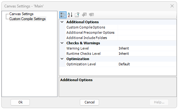
The Custom Compile Settings dialog inputs are described in the following sections. These options may be used to override the project-based, advanced compiler options set in the Project Settings dialog, under the Fortran tab.
These options are related resource files and compiler options.
Custom Compile Options: Enter custom command line options to customize the compilation of this, specific resource file.
Additional Precompiler Options: Enter compiler command line, pre-compiler options to customize the compilation of this, specific resource file.
Additional Include Folders: Designate additional compiler folders, from which to find compile time resources.
These options relate to checks and warning levels.
Warning Level: Select the level to use for displaying warnings, while the simulation is building. Select Inherit to use project-based settings.
Runtime Checks Level: Select the level of runtime checks to perform during runtime (may affect simulation performance). Select Inherit to use project-based settings.
These options are related to runtime optimization.
Optimization: Increasing optimization level may improve simulation runtime performance, but at the cost of additional compile time. Debugging is best performed with optimization off.