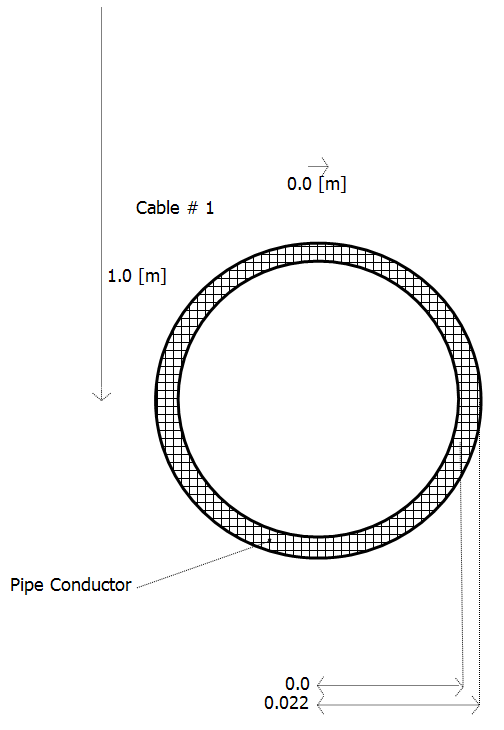
This cable model is simply an empty pipe conductor, which may or may not possess an outer insulating layer.
|
More: |
Pipe ConfigurationPipe Configuration
|
Name for Identification |
Text |
Optional text parameter for identification of the component. |
||
|
|
|
|
|
|
|
Cable Number |
|
Choice |
|
Select a number between 1 to 12. This parameter is used for the numbering of multiple cables in the same right of way. |
|
|
|
|
|
|
|
Placement in Relation to Ground Plane |
Choice |
Choose whether this cable is placed above (Aerial) or below (Underground) the ground plane. |
||
|
|
|
|
|
|
|
Depth Below Ground Surface |
|
REAL |
Literal |
Enter the depth of the pipe centre-point below the earth surface [m]. The y-coordinate of all coax cables included in this pipe must be relative to this depth. |
|
|
|
|
|
|
|
Loss Tangent is Defined At |
REAL |
Literal |
Enter the frequency at which loss tangents are defined [Hz]. |
|
|
|
|
|
|
|
|
Horizontal Translation from Centre |
|
REAL |
Literal |
Enter the translation of the pipe centre-point along the horizontal (x) axis [m]. This value is relative to a local x=0 point, which is derived given the position of all cables in this segment. The x-coordinate of all coax cables included in this pipe must be relative to this depth. |
|
|
|
|
|
|
|
Layer Configuration |
|
Choice |
|
Select the configuration of the cable layers. C and I represent conducting and insulating layer respectively. |
|
|
|
|
|
|
|
Layer Thickness is Specified As |
|
Choice |
|
Select the manner in which the layer thicknesses are specified. If radial from centre is selected, enter the distance from the centre-point to the outer radius of the layer. |
|
|
|
|
|
|
|
Detailed Graphic Layers |
|
Choice |
|
Select show or hide. |
Pipe Conductor DataPipe Conductor Data
|
Resistivity |
|
REAL |
Literal |
Enter the resistivity of the corresponding conductor or insulator [Wm]. |
|
|
|
|
|
|
|
Relative Permeability |
|
REAL |
Literal |
Enter the relative permeability of the corresponding insulator. |
|
|
|
|
|
|
|
Inner Radius |
|
REAL |
Literal |
Enter the inner radius of the corresponding conductor [m]. |
|
|
|
|
|
|
|
Outer Radius |
|
REAL |
Literal |
Enter the outer radius of the corresponding conductor [m]. |
|
|
|
|
|
|
|
Resistivity |
|
REAL |
Literal |
Enter the resistivity of the corresponding conductor or insulator [Wm]. |
Outer Insulator Layer DataOuter Insulator Layer Data
|
Relative Permittivity |
|
REAL |
Literal |
Enter the relative permittivity of the corresponding insulator. |
|
|
|
|
|
|
|
Loss Tangent |
|
REAL |
Literal |
Enter the loss tangent of the insulator. |
|
|
|
|
|
|
|
Relative Permeability |
|
REAL |
Literal |
Enter the relative permeability of the corresponding insulator. |
|
|
|
|
|
|
|
Outer Radius |
|
REAL |
Literal |
Enter the outer radius of the corresponding insulator [m]. |
|
|
|
|
|
|
|
Thickness |
|
REAL |
Literal |
Enter the thickness of the corresponding insulator [m]. |
Inner Cable DataInner Cable Data
Note that these parameters are identical to those of the Coaxial Cable model.
Conductor Data:
|
Resistivity |
|
REAL |
Literal |
Enter the resistivity of the corresponding conductor [Wm]. |
|
|
|
|
|
|
|
Relative Permeability |
|
REAL |
Literal |
Enter the relative permeability of the corresponding conductor. |
|
|
|
|
|
|
|
Inner Radius |
|
REAL |
Literal |
Enter the inner radius of the corresponding conductor. If this is the central solid conductor, enter 0.0 [m] |
|
|
|
|
|
|
|
Outer Radius |
|
REAL |
Literal |
Enter the outer radius of the corresponding conductor. |
|
|
|
|
|
|
|
Thickness |
|
REAL |
Literal |
Enter the thickness of the conducting layer [m]. Note that this parameter is enabled only if Layer thickness is specified as | actual thickness is selected. |
Insulator Data:
|
Semi-Conducting Layers |
|
Choice |
|
Select whether or not there are semi-conducting layers present in this cable. Semi-conductor layers may only be included between the core and 1st conducting layers. |
|
|
|
|
|
|
|
Relative Permittivity |
|
REAL |
Literal |
Enter the relative permittivity of the corresponding insulator. |
|
|
|
|
|
|
|
Relative Permeability |
|
REAL |
Literal |
Enter the relative permeability of the corresponding insulator. |
|
|
|
|
|
|
|
Outer Radius |
|
REAL |
Literal |
Enter the outer radius of the corresponding insulator [m]. |
|
|
|
|
|
|
|
Thickness |
|
REAL |
Literal |
Enter the thickness of the insulating layer [m]. Note that this parameter is enabled only if Layer thickness is specified as | actual thickness is selected. |
|
|
|
|
|
|
|
Inner Semi-Conductor Layer Thickness |
|
REAL |
Literal |
Enter the thickness of the inner semi-conducting layer (between insulator and core conductor) [m].
NOTE: This value should not be included as part of the conductor or insulator dimensions. The line constants program will take care of the semi-conductor layer automatically, given this thickness. |
|
|
|
|
|
|
|
Outer Semi-Conductor Layer Thickness |
|
REAL |
Literal |
Enter the thickness of the outer semi-conducting layer (between insulator and 1st conducting layer) [m].
NOTE: This value should not be included as part of the conductor or insulator dimensions. The line constants program will take care of the semi-conductor layer automatically, given this thickness. |