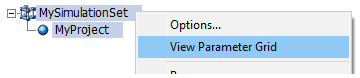
Viewing Simulation Properties in the Parameter Grid
Simulation sets are an inherent part of the workspace, and can be viewed and modified from within the workspace primary window.
The concept of a simulation set provides the foundation for parallel computing in PSCAD. A simulation set is a container of sorts, used to compartmentalise and configure groups of simulations. All simulations placed within a particular set are launched simultaneously (in parallel), utilising all processing resources available. If multiple simulation sets have been defined, then each set is run sequentially as they appear in the list of sets: In the image above for example, SimulationSet1 will launch and run the ieee_ssr_bench and Study_2 projects simultaneously. Once finished, SimulationSet2 will launch and run the Cigre_Benchmark project. The sequential launching of all sets is automatic, if the user selects to run all sets.
The image below illustrates a scenario on how resources are utilised when running simulations in sets. In this example, there are two sets, one containing 5 simulations, and the other 9. As the local processor is 8-core, then there are 7 cores available (one used by PSCAD) to run the processes. The second set contains more simulations than there are cores available (9 simulations, 7 cores). In these situations, the operating system will force all 9 processes to be shared amongst the available resources. Obviously, the more cores available for parallel processing, the larger the sets of simulations can be run without any impact on efficiency.
|
|
|
|
Set Containing 5 Simulations Uses One Core For Each Directly |
Set Containing 9 Simulations Must Share the 7 Cores Available (Decreased Efficiency) |
Only projects loaded under the Projects branch in the workspace primary window may be added as a Simulation in a Simulation Set. Simulation sets and corresponding settings are all stored as part of the workspace.
For more information on manipulating simulation sets, see the following topics (found in Operation and Feature Overview | Workspace):
Adding a Simulation to a Simulation Set
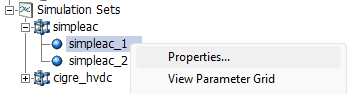
To invoke the Simulation Set Properties dialog, right-click on an existing simulation set and select Properties...
The following describes the properties available for simulation sets:
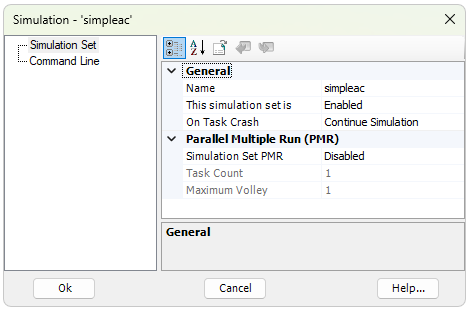
General:
Name: The name of the simulation set. Name length must be 30 characters or less, and must only contain valid characters.
This simulation set is: If set to Disabled, this simulation set will be excluded when the Run All command is executed. See Running Simulations Sets.
On Task Crash: Select to Continue Simulation or not on a task crash. If a single EMTDC instance crashes or dies during a simulation set run, that simulation set will become stuck, continuously waiting for the dead task. This could put an exceedingly large amount of stress on a machine until the task is manually killed.
Parallel Multiple Run (PMR):
Simulation Set PMR: Control to enable/disable a simulation set level, parallel multiple run (PMR), which can be used to perform a PMR on a Parallel Network Interface (PNI) simulation. Use caution when enabling this function, as the number of parallel tasks will become the product of the simulation set, times the task count set in the individual simulation tasks.
Task Count: Specify the total number of times a project will execute each with a unique rank number.
Maximum Volley: Specifies the maximum number of tasks to execute in parallel. Note that this number is limited by your EMTDC license (contact sales@pscad.com for more information).
Pre and post-run processes may be performed between simulation set runs. For example, a batch file can be used to copy or move EMTDC output files to another folder before the next simulation set is started.
Post-Run Process: Specify an executable (*.exe) or batch (*.bat) file to run, after the simulation set has completed.
Wait (Post-Run): Select Wait or Do Not Wait. If wait is selected, PSCAD will wait for the Post-Run Process to complete before continuing with the simulation set run.
Pre-Run Process: Specify an executable (*.exe) or batch (*.bat) file to run, before the simulation set has completed.
Wait (Pre-Run): Select Wait or Do Not Wait. If wait is selected, PSCAD will wait for the Pre-Run Process to complete before continuing with the simulation set run.
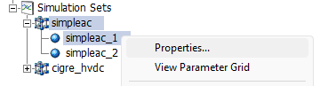
To invoke the Simulation Properties dialog, right-click on an existing simulation and select Properties...
The following describes the options available for simulations:
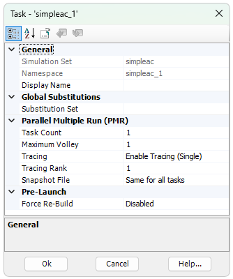
Simulation Set: Display only. This is the simulation set, in which this simulation is housed.
Namespace: Display only. This is the associated project namespace name.
Display Name: Enter a name that will be used only for display in the workspace pane.
Substitution Set: Choose which global substitution set is to be associated with this simulation. See Global Substitutions Pane for a detailed discussion on global substitutions.
Task Count: Specify the total number of times a simulation will execute. Each simulation can launch multiple instances of itself for batch processing, each assigned a rank number used to isolate control behaviour. See Parallel Multiple Run (PMR) for more details.
Maximum Volley: Specify the maximum number simulations to launch in parallel. This number should be chosen based on the number of processor cores available to you. The default maximum is 8, which is limited by your PSCAD license. To increase this limit, please contact the PSCAD Sales Desk (sales@pscad.com).
Tracing: Select the level of tracing you prefer for this simulation. As a cautionary note, tracing should only be enabled during a testing and debugging. When performing bulk simulations (ex. parametric studies), tracing should remain disabled, as simulation speed can be greatly affected. If Enable Tracing (Single) is selected, you must be specify a Tracing Rank. For more details on tracing, see Volley Launch (SPMD).
Tracing Rank: Specify which simulation task (rank number) will provide tracing (or plotting) information back to PSCAD. For example, if the Task Count is set to 10, then there are 10 possible simulations that can be used as a 'tracer'. See Volley Launch (SPMD) for more details.
Snapshot File: If starting from a snapshot file, this option allows you to select whether to use the same snapshot file for all tasks, or a specific snapshot file for each task, based on a unique rank number.
Force Rebuild: Force a rebuild of the project associated with this simulation, prior to launch and between runs. When enabled, a clean action is performed on the project temporary folder, thereby forcing a rebuild of the project. Note that enabling this option can result in lost data (ex. snapshot and output files).
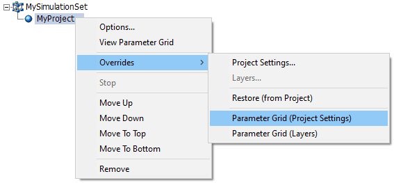
Managing simulation and simulation set options can become unruly when many simulation sets are defined in the workspace. Thankfully, the Parameter Grid may be utilised for these tasks. Simulation set options, simulation options, simulation project setting overrides, and simulation layer overrides, may all be managed through the parameter grid:
|
|
|
|
|
Simulation Set Properties |
Simulation Properties |
Project Setting Overrides and Layer Overrides |
Here is an example simulation options view in the parameter grid:
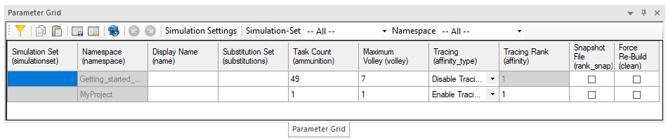
It is possible to override both the project settings and project layer configurations, in the context of a specific simulation task. This is powerful in that it enables you to launch multiple simulation tasks, based on the same project, where the settings or layer configurations are unique to each task.
To open the project or layers override dialog, right-click on a simulation task and select Overrides | Project Settings... or Layers...
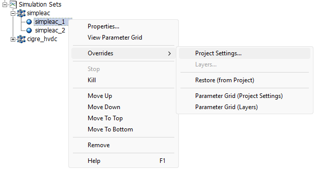
NOTE: If the project does not contain any layers, the Layers... option will be disabled
The Project Overrides dialog contains four categories, but there really only two parts to the dilaog: Runtime and Compiler. Runtime gives you access to the Project Settings Runtime tab for the project associated with this simulation task, whereas compiler gives you access to the advanced Fortran, MATLAB and C compiler options, under the Project Settings Fortran tab.

To override a Runtime or Compiler setting, click on the Runtime Overrides or the Compiler Overrides categories to bring up that form. For the Runtime Overrides, the dialog will appear as below:

Be default, all properties in this form are set to Use Default. This simply means to use the setting value set in the project settings. However, if you want to change or override one or more of these settings, select Override from the setting drop list. In the above image, it has been selected to enable override of the simulation time step.
Going back to the Runtime category, we can see that the simulation time step tob used when this task is launched, will be 100 us.

NOTE: The original project setting in the associated project will remain unchanged. This information is saved with the simulation task, not the project itself.
The Layer Overrides dialog functions in the same manner as the Project Overrides dialog above, except it is used to configure the project layer configurations of course.