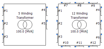
This component models a single-phase, ideal transformer that can be configured to model from five to 12 windings. Options are provided to enable a simple saturation model on a user selected winding, as well as for adding a tap changer.
|
More: |
|
Name for Identification |
Text |
Optional text parameter for identification of the component. |
||
|
Transformer MVA |
|
REAL |
Constant |
The apparent power rating of the transformer [MVA]. |
|
|
|
|
|
|
|
Base Operation Frequency |
|
REAL |
Constant |
The base frequency of the electrical system, in which the transformer resides [Hz]. |
|
|
|
|
|
|
|
Number of Windings |
|
Choice |
|
Select the number of windings, from 5 to 12. |
|
|
|
|
|
|
|
Tap Changer on Winding |
|
Choice |
|
Select None, #1, #2... #12.
Select the winding number on which to place the on-line tap changer (or none). See On-Line Tap Changer for more details. |
Leakage ReactancesLeakage Reactances
|
Leakage Reactance (#M-#N) |
|
REAL |
Constant |
The leakage reactance between winding #m and #n [pu]. |
Winding Voltages and LossesWinding Voltages and Losses
|
Winding # Line to Line Voltage (RMS) |
|
REAL |
Constant |
[kV] |
|
|
|
|
|
|
|
No Load Losses |
|
REAL |
Constant |
Core losses [pu]. |
|
|
|
|
|
|
|
Copper Losses of Winding # |
|
REAL |
Constant |
[pu] |
NOTE: See Adjusting Saturation Properties for more details on these inputs
|
Saturation Enabled |
|
Choice |
|
Select Yes or No to enable or disable the core saturation routine. |
|
|
|
|
|
|
|
Place Saturation on Winding |
|
Choice |
|
Select #1, #2... #12.
See Adjusting Saturation Properties for more details. |
|
|
|
|
|
|
|
Time to Release Flux Clipping |
|
REAL |
Constant |
Time interval from start-up in which the model will 'clip' (limit) the calculated flux linkage values. This is simply a modelling 'trick' to prevent instability at start-up [s]. |
|
|
|
|
|
|
|
Air Core Reactance |
|
REAL |
Constant |
Usually approximately twice the leakage reactance [pu]. |
|
|
|
|
|
|
|
Magnetizing Current |
|
REAL |
Constant |
The percentage of primary winding current that flows through the transformer magnetizing susceptance. This value can be calculated based on the open-circuit test results. The magnetizing susceptance is calculated based on this value [%]. |
|
|
|
|
|
|
|
Knee Voltage |
|
REAL |
Constant |
The knee point voltage corresponding to the knee point of the saturation curve [pu]. |
Internal OutputsInternal Outputs
|
Name for Magnetizing Current [kA] |
|
REAL |
Output |
Name for the magnetizing current [kA]. |
|
|
|
|
|
|
|
Name for Flux Linkage [kWb-N] |
|
REAL |
Output |
Name for the calculated flux linkage [kWb-N]. |
|
|
|
|
|
|
|
Name for Winding # Current |
|
REAL |
Output |
Name for the specified winding current [kA]. |