This cable component is used to model typical pipr-type cable systems. It is meant to simplify the construction of the pipe cable, by taking advantage of data duplication to simplify data entry, as well as provide formats more aligned with typical cable data sheets. The component can be adjusted to easily represent the following typical system configurations:
Typical values of material data are also provided by default.
|
More: |
|
Name for Identification |
Text |
Optional text parameter for identification of the component. |
||
|
|
|
|
|
|
|
Detailed Graphic Layers |
|
Choice |
|
Select show or hide. |
|
|
|
|
|
|
|
Loss Tangent is Defined At |
REAL |
Literal |
Enter the frequency at which loss tangents are defined [Hz]. |
|
|
|
|
|
|
|
|
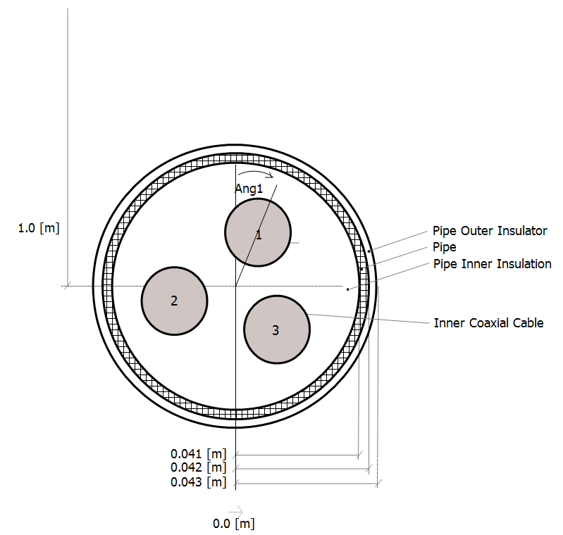
Horizontal Translation from Centre |
|
REAL |
Literal |
Enter the translation of the pipe centre-point along the horizontal (x) axis [m]. This value is relative to a local x=0 point, which is derived given the position of all cables in this segment. The x-coordinate of all coax cables included in this pipe must be relative to this depth. |
|
|
|
|
|
|
|
Depth Below Ground Surface |
|
REAL |
Literal |
Enter the depth of the pipe centre-point below the earth surface [m]. The y-coordinate of all coax cables included in this pipe must be relative to this depth. |
|
|
|
|
|
|
|
Placement in Relation to Ground Plane |
|
Choice |
|
Select Underground or Aerial. |
|
|
|
|
|
|
|
Eliminate Pipe |
|
Choice |
|
Choose whether or not to mathematically eliminate the pipe conductor. |
|
|
|
|
|
|
|
Pipe Number |
|
Choice |
|
Select 1 to 5.
This is a unique pipe number, used for sorting multiple pipes in the same right-of-way. |
|
Pipe Outer Insulator Layer |
|
Choice |
|
Choose whether or not to include an insulating layer between the pipe and ground. Note that if no insulation layer is present, the conductor will be mathematically eliminated. |
|
|
|
|
|
|
|
Eliminate Pipe |
|
Choice |
|
Choose whether or not to mathematically eliminate the pipe conductor. |
|
|
|
|
|
|
|
Insulator Outer Radius |
|
REAL |
Literal |
Enter the outer radius of the insulator [m]. |
|
|
|
|
|
|
|
Insulator Relative Permittivity |
|
REAL |
Literal |
Enter the relative permittivity of the insulator. |
|
|
|
|
|
|
|
Insulator Loss Tangent |
|
REAL |
Literal |
Enter the loss tangent of the insulator. |
|
|
|
|
|
|
|
Insulator Relative Permeability |
|
REAL |
Literal |
Enter the relative permeability of the insulator. |
|
|
|
|
|
|
|
Conductor Outer Radius |
|
REAL |
Literal |
Enter the outer radius of the conductor [m]. |
|
|
|
|
|
|
|
Resistivity |
|
REAL |
Literal |
Enter the resistivity of the conductor [Wm]. |
|
|
|
|
|
|
|
Conductor Relative Permeability |
|
REAL |
Literal |
Enter the relative permeability of the conductor. |
Inner Cable ConfigurationInner Cable Configuration
|
Cable Layers |
|
Choice |
|
Select the configuration of the cable layers. C and I represent conducting and insulating layer respectively. |
|
|
|
|
|
|
|
Cable Configuration |
|
Choice |
|
Select trefoil-touching or trefoil non-touching. |
|
|
|
|
|
|
|
Angle of Cable #1 in Degrees |
|
REAL |
Literal |
Enter the angle of cable #1 in relation to the vertical starting point [deg]. |
|
|
|
|
|
|
|
Cross-Bonding or Conductor Elimination |
|
Choice |
|
Select whether to enable or disable. |
|
|
|
|
|
|
|
Ideal Cross-Bonding/Transposition Is |
|
Choice |
|
Choose whether or not to enable or disable the ideal cross-bonding feature. |
|
|
|
|
|
|
|
Cross-Bonding/Transposition Group |
|
Choice |
|
Select the group number to which this cable belongs. See Ideal Cross-Bonding for more details.
NOTE: Each cable group defines a cross-bonded system of three cables. Each cable in the group should have the same set of cross-bonded conductors. There can be multiple cross-bonded cable groups or a combination of cross-bonded and non cross-bonded cables (ex. a cable system with three cross-bonded and two non cross-bonded cables). Usually in a cross-bonded cable system, only sheaths are transposed at regular intervals. However (if required), any other conductor can also be be transposed.
In some applications, the inner conductor is transposed other than the sheath to obtain a balanced system. This can be accomplished by enabling cross-bonding/transposition of both inner conductor and sheath. In some practical applications, the sheaths at major section points (must consist of three cable sections) of the cross-bonded cable are connected to the ground. This can be approximated by mathematically eliminating the sheath of the three cables in the group (i.e. conductor layer elimination). |
|
|
|
|
|
|
|
Transposition of Conducting Core/Layers |
|
Choice |
|
Use these options to specify which conductors are to be included in the cross-bonding. See Ideal Cross-Bonding for more details. |
|
|
|
|
|
|
|
Conductors to Eliminate |
|
Choice |
|
Choose which conducting layers to eliminate (if any). Select none to disable conductor elimination. If specify is selected, then you must specify which conductors are to be eliminated in the following parameters. |
Inner Cable DataInner Cable Data
Cable Dimensions:
|
Layer Thickness is Specified As |
|
Choice |
|
Select the manner in which the layer thicknesses are specified. If radial from centre is selected, enter the distance from the centre-point to the outer radius of the layer. |
|
|
|
|
|
|
|
Conductor Inner Radius (Enter 0.0 for Solid) |
|
REAL |
Literal |
Enter the inner radius of the conductor [m]. |
|
|
|
|
|
|
|
Conductor/Sheath/ Armour/Outer Conductor |
|
REAL |
Literal |
Enter the outer radius or thickness of the corresponding conductor [m]. Depends on Layer Thickness is Specified As. |
|
|
|
|
|
|
|
Insulating Layers |
|
REAL |
Literal |
Enter the outer radius or thickness of the corresponding insulator [m]. Depends on Layer Thickness is Specified As. |
Material Properties:
|
Conductor Property Given As |
|
Choice |
|
Select either DC Resistance or one of the several Resistivity options. |
|
|
|
|
|
|
|
DC Resistance/Resistivity |
|
REAL |
Literal |
Enter the DC resistance or resistivity of the corresponding conductor [W/km or Wm]. Depends on Conductor Property Given As. |
|
|
|
|
|
|
|
Insulation Property Given As |
|
Choice |
|
Select either Capacitiance or one of the several Relative Permittivity options. |
|
|
|
|
|
|
|
Loss Tangent |
|
REAL |
Literal |
Enter the loss tangent of the insulator. |
|
|
|
|
|
|
|
Capacitance/Relative Permittivity |
|
REAL |
Literal |
Enter the capcitance or the relative permittivity of the insulator. Depends on Insulation Property Given As. |
Temperature Dependency:
|
Temperature Correction for Conductor Resistances |
|
Choice |
|
Select whether to enable or disable.. |
Additional Material Properties:
|
Loss Tangent is Defined At |
REAL |
Literal |
Enter the frequency at which loss tangents are defined [Hz]. |
|
|
|
|
|
|
|
|
Relative Permeability |
|
REAL |
Literal |
Enter the relative permeability of the corresponding conductor or insulator. |
|
|
|
|
|
|
|
Semi-Conducting Layers |
|
Choice |
|
Select whether or not there are semi-conducting layers present in this cable. Semi-conductor layers may only be included between the core and 1st conducting layers. |
|
|
|
|
|
|
|
Inner Semi-Conductor Layer Thickness |
|
REAL |
Literal |
Enter the thickness of the inner semi-conducting layer (between insulator and core conductor) [m].
NOTE: This value should not be included as part of the conductor or insulator dimensions. The line constants program will take care of the semi-conductor layer automatically, given this thickness. |
|
|
|
|
|
|
|
Outer Semi-Conductor Layer Thickness |
|
REAL |
Literal |
Enter the thickness of the outer semi-conducting layer (between insulator and 1st conducting layer) [m].
NOTE: This value should not be included as part of the conductor or insulator dimensions. The line constants program will take care of the semi-conductor layer automatically, given this thickness. |