This component is a more 'convenient' version of the standard synchronous machine that does not include equivalent circuit data format, advanced options, etc. If these are necessary, please use the standard synchronous machine component.
This component includes an option to model two damper windings in the Q-axis. The speed of the machine may be controlled directly by inputting a positive value into the w input of the machine, or a mechanical torque may be applied to the Tm input.
The desired steady-state conditions may be known from a load flow. Once the steady-state is reached in the simulation, faults, disturbances etc. may be applied to see the transient response. See Start-up and Initialization for a description of these advanced options.
NOTE: Convenient version means the simplification of the input parameters and the accuracy of the model is not changed.
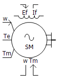
Tm: Imports the synchronous machine mechanical torque in per-unit.
Ef: Imports the synchronous machine field voltage in per-unit.
w: Imports the synchronous machine rotor speed in rad/s. It is visible only if the input parameter Multi-mass Interface is selected as Enabled.
Tm0: Outputs the initialized mechanical torque in per-unit. It is visible only if the input parameters Output Initialized Mechanical Torque (Tm0) is selected as Yes.
w: Outputs the rotor speed in per-unit or rad/s.
Tm: Outputs the mechanical torque in per-unit.
Te: Outputs the electrical torque in per-unit.
Ef0: Outputs the initialized field voltage in per-unit. It is visible only if the input parameters Output Initialized Field Voltage (Ef0) is selected as Yes.
If: Outputs the filed current in per-unit.
 : This electrical port is used to interface with the exciter. It is visible only if the input parameters Interface to Exciter is selected as Yes.
N: This electrical port is neutral connection points. It is visible only if the input parameters External Neutral Connection is selected as Enabled.
ABC: These electrical ports are used to connect with the external power systems, which can be single line view or 3 phase view.
|
More: |
Interfacing to the Multi-Mass Torsional Shaft |
|
Machine Name |
|
Text |
|
Just an identifier. A name should be entered here for easy identification. |
|
|
|
|
|
|
|
Rated Voltage |
|
REAL |
Constant |
Enter the machine rated line-to-line voltage [kV]. |
|
|
|
|
|
|
|
Base Frequency |
|
REAL |
Constant |
Enter the base system frequency to which the machine is initialized at time t = 0.0s [Hz]. If the rotor is locked during initialization, the machine will run at this constant frequency [Hz]. |
|
|
|
|
|
|
|
Iron Loss Resistance |
|
REAL |
Constant |
This value is provided as a shunt resistance at the machine terminals and should be between 66.7 and 300 [pu]. |
|
|
|
|
|
|
|
Multi-Mass Interface |
|
Choice |
|
Select Enable or Disable. See Interfacing to the Multi-Mass Torsional Shaft for more details. |
|
|
|
|
|
|
|
Inertia Constant |
|
REAL |
Constant |
This input represents the stored energy in the rotor at rated speed per machine rating and is typically between 2.0 and 6.0 [MWs/MVA].
This parameter is enabled only if Muti-Mass Interface | Disable is selected. |
|
|
|
|
|
|
|
Mechanical Friction and Windage |
|
REAL |
Constant |
Enter the mechanical damping constant. This input is typically between 0.0 and 0.05 (0.0 meaning no frictional losses). See Mechanical Friction and Windage for more details [pu].
This parameter is enabled only if Muti-Mass Interface | Disable is selected. |
|
|
|
|
|
|
|
Machine Scaling Factor |
|
Choice |
|
Select Yes or No. See Coherent Machines for more details |
|
|
|
|
|
|
|
Number of Coherent Machines |
|
REAL |
Variable |
Enter the number of machines acting coherently. See Coherent Machines for more details.
This parameter is enabled only if Machine Scaling Factor | Yes is selected. |
|
|
|
|
|
|
|
External Neutral Connection |
|
Choice |
|
Select Enable or Disable.
NOTE: Care must be taken when the machine is scaled to model several machines. If the external connections are used, the connected elements should be scaled appropriately. See Coherent Machines for more details. |
|
|
|
|
|
|
|
Neutral Series Resistance |
|
REAL |
Constant |
The real component of fundamental frequency impedance, which is connected between the machine neutral and ground [pu].
This parameter is enabled only if External Neutral Connection | Disabled is selected. |
|
|
|
|
|
|
|
Neutral Series Reactance |
|
REAL |
Constant |
The reactive component of fundamental frequency impedance, which is connected between the machine neutral and ground [pu].
This parameter is enabled only if External Neutral Connection | Disabled is selected. |
Generator Data FormatGenerator Data Format
|
No. of Q-Axis Damper Windings |
|
Choice |
|
Select the appropriate number of q-axis windings. |
|
|
|
|
|
|
|
Armature Resistance As |
|
Choice |
|
Select Time Constant or Resistance. See Data Entry Formats for more details. |
|
|
|
|
|
|
|
Saturation |
|
Choice |
|
Select Enabled or Disabled. The D-axis saturation is disabled by default. When enabled, a saturation characteristic is applied as given by data points in the Saturation Curve section of the component properties. See Saturation Curve for more details. |
|
|
|
|
|
|
|
Armature Resistance [Ra] |
|
REAL |
Constant |
Enter the armature resistance [pu]. This is only enabled if the Armature Resistance As | Resistance is selected. |
|
|
|
|
|
|
|
Armature Time Constant [Ta] |
|
REAL |
Constant |
Enter the armature time constant. This is only enabled if the Armature Resistance As | time Constant is selected. |
|
|
|
|
|
|
|
Stator Leakage Reactance [Xl] |
|
REAL |
Constant |
Stator Leakage Reactance [pu]. Stator Leakage Reactance must be less than the Direct-Axis Reactance, Transient Reactance and Sub-Transient Reactance. |
|
|
|
|
|
|
|
Unsaturated Reactance |
|
REAL |
Constant |
Xd, Xq [pu] |
|
|
|
|
|
|
|
Unsaturated Transient Reactance |
|
REAL |
Constant |
Xd', Xq' [pu] |
|
|
|
|
|
|
|
Unsaturated Transient Time (Open) |
|
REAL |
Constant |
Tdo', Tqo' [s] |
|
|
|
|
|
|
|
Unsaturated Sub-Transient Reactance |
|
REAL |
Constant |
Xd", Xq" [pu] |
|
|
|
|
|
|
|
Unsaturated Sub-Transient Time (Open) |
|
REAL |
Constant |
Tdo", Tqo" [s] |
Saturation CurveSaturation Curve
Note: This category is enabled only if Generator Data Format | Saturation | Enabled is selected.
|
Number of Data Points Available |
|
Choice |
|
|
|
|
|
|
|
|
|
Point # - Current |
|
REAL |
Constant |
Enter the I data point for the mutual magnetizing inductance saturation curve. See Saturation Curve for more details [pu] |
|
|
|
|
|
|
|
Point # - PU Voltage |
|
REAL |
Constant |
Enter the V data point for the mutual magnetizing inductance saturation curve. See Saturation Curve for more details [pu] |
Initial ConditionsInitial Conditions
|
Terminal Voltage Magnitude at Time = 0- |
|
REAL |
Constant |
Terminal voltage magnitude at start-up [pu]. |
|
|
|
|
|
|
|
Terminal Voltage Phase at Time = 0- |
|
REAL |
Constant |
Terminal voltage phase angle at start-up [deg]. Care must be taken if the machine is connected through a Y-D transformer, with the bus side on Y and the machine on D. If the bus phase angle is being determined from a conventional load flow program, Y-D transformations are not taken into account. Therefore, 30° must be subtracted from this angle if obtained from load flow calculations [rad] |
|
|
|
|
|
|
|
Terminal Real Power at Time = 0- |
REAL |
Constant |
Terminal active power at start-up [MW]. This parameter is available only if the Type of Settings for Initial Condition | Terminal Power Flow Condition is selected. |
|
|
|
|
|
|
|
|
Terminal Reactive Power at Time = 0- |
REAL |
Constant |
Terminal reactive power at start-up [MVAR]. This parameter is available only if the Type of Settings for Initial Condition | Terminal Power Flow Condition is selected. |
|
|
|
|
|
|
|
|
Transition Time (Voltage Source Mode to Machine Mode) |
REAL |
Constant |
The time when the machine is changed from a voltage source to a machine [s]. |
|
|
|
|
|
|
|
|
Transition Time (Fixed Mechanical Speed Mode to Rotor Dynamic Mode) |
REAL |
Constant |
The time when the rotor is released [s]. |
|
|
|
|
|
|
|
|
Ramp Time to Rated (Start as a Source) |
REAL |
Constant |
This parameter is used to provide a 'soft start', when starting from time = 0.0 as a source, so that network transients are minimized [s]. Only used when the machine is started as a Source. |
Interface To Machine ControllersInterface To Machine Controllers
|
Output Initialized Field Voltage (Ef0) |
|
Choice |
|
Select Yes,
or No.
If Yes, the required field voltage is used to initialize the exciter, so that the machine can be switched from source mode to machine mode smoothly. See Start-up and Initialization for more details |
|
|
|
|
|
|
|
Interface to Exciter? |
|
Choice |
|
Select Yes, or No. If Yes, the parameters related to exciters will show. |
|
|
|
|
|
|
|
Terminal Information to Exciter |
|
Choice |
|
Select Terminal Voltage, Terminal Current or Both Voltage and Current.
This parameter is available only if the Interface to Exciter? | Yes is selected. |
|
|
|
|
|
|
|
Smoothing Time Constant |
|
REAL |
Variable |
Time constant used for smoothing out terminal measurements before supplying to exciter [s]. This parameter is available only if the Interface to Exciter? | Yes is selected. |
|
|
|
|
|
|
|
Exciter Initialization Signal |
|
Text |
|
Give a variable name.
|
|
|
|
|
|
|
|
Output Initialized Mechanical Torque (Tm0) |
|
Choice |
|
Select Yes
or No. If Yes, the required mechanical torque is used to initialize the turbine and/or governor, so that the machine can be switched from 'locked-rotor' to 'free running' mode smoothly. See Start-up and Initialization for more details |
|
|
|
|
|
|
|
Interface to Governor/Turbine? |
|
Choice |
|
Select Yes or No. If Yes, the parameters related to Governor/Turbine will show. |
|
|
|
|
|
|
|
Governor/Turbine Initialization Signal |
|
Text |
|
Give a variable name. This will change its assigned value from 0 to 1 when the machine is switched from a 'constant speed operation' to a 'normal machine'. Use this variable in any governor/turbine models to initialize them. |
Output Variable NamesOutput Variable Names
|
Output Speed |
|
Choice |
|
Select per-unit or radians per second, depending on that needed by the Governor/Turbine models interfaced. |
|
|
|
|
|
|
|
Real Power |
|
REAL |
Output |
Real power output of the machine. (+) - power flowing out [pu] |
|
|
|
|
|
|
|
Reactive Power |
|
REAL |
Output |
Reactive power output of the machine. (+) - power flowing out [pu] |
|
|
|
|
|
|
|
Neutral Voltage Real |
|
REAL |
Output |
Voltage at the machine neutral (star) point [kV]. This parameter is available only if the External Neutral Connection | Disable is selected. |
|
|
|
|
|
|
|
Neutral Current to Ground (kA) |
|
REAL |
Output |
Machine neutral current [kA]. This parameter is available only if the External Neutral Connection | Disable is selected. |
|
|
|
|
|
|
|
Load Angle; Gen + |
|
REAL |
Output |
This is the phase difference between the internal voltage and the terminal voltage and is responsible for pushing the power in/out of machine. This angle should not be confused with Internal Phase A Angle with Respect to sin(wt) as described below [rad] |
|
|
|
|
|
|
|
Rotor Mechanical Angle |
|
REAL |
Output |
This is a saw tooth wave from 0 to 2p radians. The value indicates the position of the rotor [rad]. |
|
|
|
|
|
|
|
Internal Phase 'A' Angle with Respect to sin(wt) |
|
REAL |
Output |
This is calculated as Wang = Phase angle of Terminal Voltage + Lang + Integral of (wpu - 1.0) x d(t). |
|
|
|
|
|
|
|
Steady Electric Torque |
|
REAL |
Output |
Smoothed output of the electrical torque of the machine [rad] |