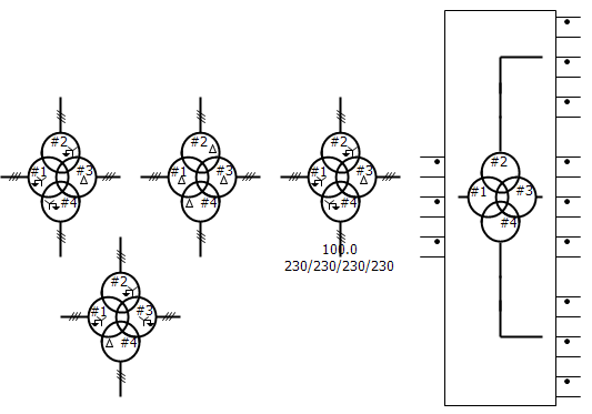
This component represents a mode of a 3-phase, 2-winding transformer, based on the principle of duality.
It can be used to model a multi-limb transformer or a bank of single-phase transformers. Several methods of entering transformer core, non-linearity parameters are available. Optional stray capacitances are also available.
For additional help with parameter determination, see reference [13].
|
More: |
|
Transformer Name |
|
Text |
|
Just an identifier. A name should be entered here to avoid compilation warnings |
|
|
|
|
|
|
|
Transformer Core Model |
|
|
|
Select from 3 phase bank, 5 limb, 3 limb or 3 limb with zero sequence, to represent the transformer core construction. |
|
|
|
|
|
|
|
3-Phase Transformer MVA |
|
REAL |
Constant |
The 3-phase apparent power rating of the transformer [MVA]. |
|
|
|
|
|
|
|
Base Operation Frequency |
|
REAL |
Constant |
The base frequency of the electrical system, in which the transformer resides [Hz]. |
|
|
|
|
|
|
|
Copper Losses of Winding # |
|
REAL |
Constant |
Enter the total copper losses based on the transformer MVA [pu]. |
|
|
|
|
|
|
|
Core Eddy Current Losses |
|
REAL |
Constant |
Enter the core eddy current, less the portion of no-load losses, based on the transformer rating. Hysteresis loss may also be added here, if hysteresis is not modeled [%]. |
|
|
|
|
|
|
|
Positive Sequence Leakage Reactance (#-#) |
|
REAL |
Constant |
Positive sequence leakage reactance, entered based on transformer base impedance [pu]. |
|
|
|
|
|
|
|
Display Details |
|
Choice |
|
Select Yes or No. Displays MVA and winding voltages near the component. |
Winding SettingsWinding Settings
|
Open Terminals? |
|
Choice |
|
Select Yes or No. Select Yes to get access to all transformer terminals. |
|
|
|
|
|
|
|
Winding # Connection |
|
Choice |
|
Select the connection type for the specified winding # - Y or D connected. |
|
|
|
|
|
|
|
Winding # Clock Position |
|
Choice |
|
Select the transformer vector group.
Regardless of RMS winding voltages, winding 1 is the reference winding (Y or D) and the phase shift is imposed on winding 2 (Y or D). |
|
|
|
|
|
|
|
Y Neutral for Winding # |
|
Choice |
|
Select Solidly grounded, Ungrounded or External, to represent the type of - connection neutral for the designated winding. |
|
|
|
|
|
|
|
Winding # Line to Line Voltage (RMS) |
|
REAL |
Constant |
The RMS voltage rating of the corresponding winding # [kV]. |
|
|
|
|
|
|
|
Single Phase Winding # Voltage (RMS) |
|
REAL |
Constant |
Enter the RMS voltage rating across a single, specified winding [kV]. |
Magnetisation BranchMagnetisation Branch
NOTE: See Adjusting Saturation Properties and Transformer Magnetic Hysteresis for more details on these inputs. The parameters in this category are visible based on the settings of choice parameter Magnetization Model.
|
Magnetization Model |
|
Choice |
|
Select the type of magnetizing branch from Linear, Basic hysteresis, Jiles-Atherton hysteresis, V-I with aspect ratios, B-H with aspect ratios or B-H with dimensions. |
|
|
|
|
|
|
|
Excitation Current |
|
REAL |
Constant |
Enter the RMS exciting current as a percentage of base current [%]. |
|
|
|
|
|
|
|
Air Core Reactance |
|
REAL |
Constant |
Enter the air core reactance based on transformer base impedance [pu]. |
|
|
|
|
|
|
|
Knee Voltage for Winding-Limb |
|
REAL |
Constant |
Enter the knee point voltage corresponding to saturation curve for winding-limb [pu]. |
|
|
|
|
|
|
|
Loop Width |
|
REAL |
Constant |
Enter the loop width as a percentage of magnetizing current [%]. |
|
|
|
|
|
|
|
Nominal Magnetic Flux Density |
|
REAL |
Constant |
Enter the nominal magnetic flux density corresponding to saturation curve [T]. |
|
|
|
|
|
|
|
# of Saturation Characteristics Points |
|
Choice |
|
Select the number of points used to represent the saturation curve. |
|
|
|
|
|
|
|
Excitation Currents Point # (I#) |
|
REAL |
Constant |
Saturation characteristics RMS current [%]. |
|
|
|
|
|
|
|
Domain Flexing Parameter |
|
REAL |
Constant |
This parameter represents the contribution of reversible magnetization process. |
|
|
|
|
|
|
|
Domain Pinning Parameter |
|
REAL |
Constant |
This parameter has a direct impact on the width of the loop [A/m]. |
|
|
|
|
|
|
|
Parameter to Adjust K with M |
|
REAL |
Constant |
This parameter adjusts domain pinning parameter with magnetization for better representation of shoulder area. |
|
|
|
|
|
|
|
Interdomain Coupling |
|
REAL |
Constant |
This is a mean field parameter corresponding to the interdomain coupling. It is typically determined experimentally. |
|
|
|
|
|
|
|
Saturated Anhysteretic Magnetization |
|
REAL |
Constant |
This parameter is typically known for a particular material and thus can be obtained from data sheets, etc. [A/m]. |
|
|
|
|
|
|
|
Coefficient # of Anhysteretic Curve |
|
REAL |
Constant |
Coefficient # of the improved anhysteretic function. This function offers more flexibility for obtaining a better overall shape of the simulated B–H loop compared to the Langevin function. |
|
|
|
|
|
|
|
Magnetic Field Intensities Point # (H#) |
|
REAL |
Constant |
Saturation characteristics magnetic field intensity H [A/m]. |
|
|
|
|
|
|
|
Magnetic Field Intensities Point # (B#) |
|
REAL |
Constant |
Saturation characteristics magnetic flux density B [T]. |
|
|
|
|
|
|
|
Remanent Flux for Core # |
|
REAL |
Constant |
Enter the remanent flux as a per-unit value of the peak flux at rated voltage [pu]. |
|
|
|
|
|
|
|
V-I Point in Linear Region - Voltage |
|
REAL |
Constant |
Typically the smallest voltage in the RMS V–I saturation curve [pu]. |
|
|
|
|
|
|
|
V-I Point in Linear Region - Excitation Current |
|
REAL |
Constant |
Typically the current corresponding to the smallest voltage in the RMS V–I saturation curve [%]. |
|
|
|
|
|
|
|
Voltages Point # (V#) |
|
REAL |
Constant |
Saturation characteristics RMS voltage [pu]. |
NOTE: The parameters in this category are enabled based on the settings of choice parameters Magnetization Model and Transformer Core Model.
|
Aspect Ratio Yoke/Winding limb Length (ly/lw) |
|
REAL |
Constant |
Enter the ratio of the effective length of the yoke over the effective length of the winding limb. |
|
|
|
|
|
|
|
Aspect Ratio Yoke/Winding limb Area (sy/sw) |
|
REAL |
Constant |
Enter the ratio of the cross sectional area of the yoke over the cross sectional area of the winding limb. |
|
|
|
|
|
|
|
Aspect Ratio Yoke/Outer limb Length (ly/lo) |
|
REAL |
Constant |
Enter the ratio of the effective length of the yoke over the effective length of the outer limb. |
|
|
|
|
|
|
|
Aspect Ratio Yoke/Outer limb Area (sy/so) |
|
REAL |
Constant |
Enter the ratio of the cross sectional area of the yoke over the cross sectional area of the outer limb. |
|
|
|
|
|
|
|
Length of Winding Limb |
|
REAL |
Constant |
Enter the effective length of the winding limb [m]. |
|
|
|
|
|
|
|
Length of Yoke |
|
REAL |
Constant |
Enter the effective length of the yoke [m]. |
|
|
|
|
|
|
|
Length of Outer Limb |
|
REAL |
Constant |
Enter the effective length of the outer limb [m]. |
|
|
|
|
|
|
|
Area of Winding Limb |
|
REAL |
Constant |
Enter the cross sectional area of the winding limb [m2]. |
|
|
|
|
|
|
|
Area of Yoke |
|
REAL |
Constant |
Enter the cross sectional area of the yoke [m2]. |
|
|
|
|
|
|
|
Area of Outer Limb |
|
REAL |
Constant |
Enter the cross sectional area of the outer limb [m2] . |
|
Tap Changer on Winding |
|
Choice |
|
Select the winding number (1 or 2) on which to place the on-line tap changer. |
|
|
|
|
|
|
|
Tap Value Entry |
|
Choice |
|
Select Internal or External (classical), as the method of entering the tap value. |
|
|
|
|
|
|
|
Tap Value |
|
REAL |
Variable |
Enter the tap value as a real number or variable name [pu]. |
|
|
|
|
|
|
|
Leakage Reactance Correction |
|
Choice |
|
Select Disabled or Enabled. Enable if per-unit value of leakage reactance depends on the tap value and correction is required. Disable if leakage reactance remains constant as a per-unit value (classical). |
|
|
|
|
|
|
|
Maximum Tap Value |
|
REAL |
Constant |
Enter the maximum tap value [pu]. |
|
|
|
|
|
|
|
Total Positive Sequence Leakage Reactance (Maximum Tap) |
|
REAL |
Constant |
Enter the leakage reactance at maximum tap based on transformer base impedance [pu]. |
|
|
|
|
|
|
|
Leakage Reactance Ratio (Zero/Positive Sequence) (Maximum Tap) |
|
REAL |
Constant |
Enter the ratio of zero sequence leakage reactance over positive sequence leakage reactance at maximum tap. |
|
|
|
|
|
|
|
Minimum Tap Value |
|
REAL |
Constant |
Enter the minimum tap value [pu]. |
|
|
|
|
|
|
|
Total Positive Sequence Leakage Reactance (Minimum Tap) |
|
REAL |
Constant |
Enter the leakage reactance at minimum tap based on transformer base impedance [pu]. |
|
|
|
|
|
|
|
Reactance Ratio (Zero/Positive Sequence) (Minimum Tap) |
|
REAL |
Constant |
Enter the ratio of zero sequence leakage reactance over positive sequence leakage reactance at minimum tap. |
Stray CapacitancesStray Capacitances
NOTE: If no name is specified, these output signals will not be monitored.
|
Shunt Capacitance at Winding #? |
Choice |
|
Select Yes to place a shunt capacitance from winding # terminal to ground. |
|
|
|
|
|
|
|
|
Capacitance Between Winding 1 & 2? |
Choice |
|
Select Yes to place a capacitance between winding 1 and 2 terminals. |
|
|
|
|
|
|
|
|
Shunt Capacitance at Winding # |
REAL |
Constant |
Enter the corresponding capacitance value [mF]. |
|
|
|
|
|
|
|
|
Capacitance Between Winding 1 & 2 |
REAL |
Output |
Enter the corresponding capacitance value [mF]. |
Internal OutputsInternal Outputs
|
Name for Flux Density of Winding Limb # |
REAL |
Output |
Enter name for flux density of winding limb # [T]. |
|
|
|
|
|
|
|
|
Name for Flux Density of Yoke #-# |
REAL |
Output |
Enter name for flux density of yoke #-# [T]. |
|
|
|
|
|
|
|
|
Name for Flux Density of Outer Limb # |
REAL |
Output |
Enter name for flux density of outer limb # [T]. |
|
|
|
|
|
|
|
|
Name for Flux Linkage of Winding Limb # |
|
REAL |
Output |
Enter name for flux linkage of winding limb # [pu]. |
|
|
|
|
|
|
|
Name for Flux Linkage of Yoke #-# |
REAL |
Output |
Enter name for flux linkage of yoke #-# [pu]. |
|
|
|
|
|
|
|
|
Name for Flux Linkage of Outer Limb # |
REAL |
Output |
Enter name for flux linkage of outer limb # [pu]. |
|
|
|
|
|
|
|
|
Name for Magnetic Field Intensity of Winding Limb # |
|
REAL |
Output |
Enter name for magnetic field intensity of winding limb # [A/m]. |
|
|
|
|
|
|
|
Name for Magnetic Field Intensity of Yoke #-# |
REAL |
Output |
Enter name for magnetic field intensity of yoke #-# [A/m]. |
|
|
|
|
|
|
|
|
Name for Magnetic Field Intensity of Outer Limb # |
REAL |
Output |
Enter name for magnetic field intensity of outer limb # [A/m]. |
|
|
|
|
|
|
|
|
Name for Magnetizing Current of Winding Limb # |
|
REAL |
Output |
Enter name for magnetizing current of winding limb # [%]. |
|
|
|
|
|
|
|
Name for Magnetizing Current of Yoke #-# |
REAL |
Output |
Enter name for magnetizing current of yoke #-# [%]. |
|
|
|
|
|
|
|
|
Name for Magnetizing Current of Outer Limb # |
REAL |
Output |
Enter name for magnetizing current of outer limb # [%]. |
|
|
|
|
|
|
|
|
Name for Winding # Current of Winding Limb # |
|
REAL |
Output |
Enter name for winding # current of winding limb # [kA]. |