This component models a multi-valve, full-bridge MMC with Thévenin equivalent circuits, which effectively increases the computational efficiency [42] [43].
The equivalent resistive circuit for a full-bridge cell has been derived as shown below:
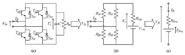
With:

The RA and RB stand for the equivalent switching resistances of the two IGBT/Diode pairs [42]. And thus, the final equivalent circuit parameters for the half-bridges are given by:

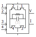
FP1, FP2, FP3, FP4: Required switching signals for the corresponding IGBT numbered as 1, 2, 3, 4.
VC: Array of capacitor voltages.
IC: Array of capacitor currents.
More: |
Name |
Text |
Optional text parameter for identification of the component. |
||
|
|
|
|
|
Number of Cells |
INTEGER |
Literal |
Number of full-bridge cells connected in series. |
|
|
|
|
|
|
Capacitance per Sub-module |
|
REAL |
Constant |
Capacitance for each half-bridge cell [mF]. |
|
|
|
|
|
Sum of Capacitor Voltages at Time Zero |
|
REAL |
Constant |
This value is used to model initial condition of the cell capacitors [kV]. |
|
|
|
|
|
Capacitor Leakage Resistance |
|
REAL |
Constant |
Leakage resistance of the cell capacitor [W]. |
|
|
|
|
|
Enable Partial Blocking? |
|
Choice |
|
Select Yes or No. |
|
|
|
|
|
IGBT ON Resistance |
|
REAL |
Constant |
ON state resistance of the IGBT [W]. |
|
|
|
|
|
IGBT OFF Resistance |
|
REAL |
Constant |
OFF state resistance of the IGBT [W]. |
|
|
|
|
|
Diode ON Resistance |
|
REAL |
Constant |
ON state resistance of the anti-parallel diode [W]. |
|
|
|
|
|
Diode OFF Resistance |
|
REAL |
Constant |
OFF state resistance of the anti-parallel diode [W]. |