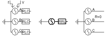
This component models a 3-phase AC voltage source, where source impedance may be specified as ideal (i.e. infinite bus). This source may be controlled through either fixed, internal parameters or variable external signals. The external inputs are described as follows:
V: Line-to-Ground, Peak Voltage Magnitude [kV]
f: Frequency [Hz]
You can connect a slider to these external inputs for a convenient runtime manual adjustment, or use a control system output for dynamic adjustment.
|
More: |
|
Source Name |
|
Text |
|
Just an identifier. A name should be entered here to avoid compilation warnings |
|
|
|
|
|
|
|
Source Impedance Type |
|
Choice |
|
Select the source impedance type as described in Impedance Data Entry |
|
|
|
|
|
|
|
Is the Star Point Grounded? |
|
Choice |
|
Select Yes to automatically ground the source common point |
|
|
|
|
|
|
|
Graphics Display |
|
Choice |
|
Select 3-phase view or single-line view |
Signal ParametersSignal Parameters
|
Specified Parameters |
|
Choice |
|
Select Behind Source Impedance or At the Terminal. The At the Terminal option should be selected if the steady-state load flow terminal data is known (i.e. V, P and Q). Behind Source Impedance should be selected if only E, q are known. See Data Format for Internal Control for more details. |
|
|
|
|
|
|
|
External Control of Voltage? |
|
Choice |
|
Select No, Yes, peak LG or Yes, RMS LL control. If No is selected, the source magnitude remains constant and is defined by the input parameter Mag. This parameter is used only if Specified Parameters | Behind Source Impedance is selected. |
|
|
|
|
|
|
|
External Control of Frequency? |
|
Choice |
|
Select Yes or No control. If No is selected, the source frequency remains constant and is defined by the input parameter Frequency. This parameter is used only if Specified Parameters | Behind Source Impedance is selected. |
|
|
|
|
|
|
|
Voltage Ramp Up Time |
|
REAL |
Constant |
The time for the source to ramp up to 1.0 pu Use a minimum ramp up time of 3 times the fundamental frequency period (i.e. 0.05 s for 60Hz and 0.06 s for 50Hz) in most cases to reduce start-up transients [s]. |
|
|
|
|
|
|
|
Frequency |
|
REAL |
Constant |
Source frequency [Hz]. This parameter is used only if External Control of Frequency? | No is selected. |
|
|
|
|
|
|
|
Base Voltage. (L-L,RMS) |
|
REAL |
Constant |
System base voltage [kV]. This parameter is used only if Specified Parameters | At the Terminal is selected. |
|
|
|
|
|
|
|
Base MVA |
|
REAL |
Constant |
System base MVA [MVA]. This parameter is used only if Specified Parameters | At the Terminal is selected. |
|
|
|
|
|
|
|
Terminal Voltage |
|
REAL |
Constant |
Terminal voltage magnitude [pu]. This parameter is used only if Specified Parameters | At the Terminal is selected. |
|
|
|
|
|
|
|
Phase Angle |
|
REAL |
Constant |
Phase angle of terminal voltage [°]. This parameter is used only if Specified Parameters | At the Terminal is selected. |
|
|
|
|
|
|
|
Real Power |
|
REAL |
Constant |
Enter the 3-phase real power P flowing at the terminal [pu]. This parameter is used only if Specified Parameters | At the Terminal is selected. |
|
|
|
|
|
|
|
Reactive Power |
|
REAL |
Constant |
Enter the 3-phase reactive power Q flowing at the terminal [pu]. This parameter is used only if Specified Parameters | At the Terminal is selected. |
|
|
|
|
|
|
|
Magnitude (AC:L-L,RMS) |
|
REAL |
Constant |
Enter the line-to-line, RMS source voltage [kV]. This parameter is used only if Specified Parameters | Behind Source Impedance is selected. |
|
|
|
|
|
|
|
Phase Shift |
|
REAL |
Variable |
Source phase shift [°]. This parameter is used only if Specified Parameters | Behind Source Impedance is selected. |
NOTE: These parameters are used only if Source Impedance Type | Ideal (R=0) is NOT selected.
|
Resistance |
|
REAL |
Constant |
Source resistance [W]. This parameter is enabled only if Source Impedance | Resistive or Source Impedance | Series R-L-C is selected. |
|
|
|
|
|
|
|
Inductance |
|
REAL |
Constant |
Source inductance [H]. This parameter is enabled only if Source Impedance | Series R-L-C or Source Impedance | Inductive is selected. |
|
|
|
|
|
|
|
Capacitance |
|
REAL |
Constant |
Source capacitance [mF]. This parameter is enabled only if Source Impedance | Series R-L-C or Source Impedance | Capacitive is selected. |
|
|
|
|
|
|
|
Resistance (Series) |
|
REAL |
Constant |
Series source resistance [W]. This parameter is enabled only if Source Impedance | R-R//L is selected. |
|
|
|
|
|
|
|
Resistance (Parallel) |
|
REAL |
Constant |
Parallel source resistance [W]. This parameter is enabled only if Source Impedance | R-R//L is selected. |
|
|
|
|
|
|
|
Inductance (Parallel) |
|
REAL |
Constant |
Parallel source inductance [H]. This parameter is enabled only if Source Impedance | R-R//L is selected. |
|
Name for Phase A Line Current [kA] |
|
REAL |
Output |
Name for the phase-A source line current [kA]. |
|
|
|
|
|
|
|
Name for Phase B Line Current [kA] |
|
REAL |
Output |
Name for the phase-B source line current [kA]. |
|
|
|
|
|
|
|
Name for Phase C Line Current [kA] |
|
REAL |
Output |
Name for the phase-C source line current [kA]. |
|
|
|
|
|
|
|
Name for 3-Phase Line Current |
|
REAL |
Output |
Name for the source line current (specific phase A, B and C) [kA]. |