PSCAD V5 is classified as a major product update, and contains many new features and functionalists when compared the previously released product, PSCAD X4.
NOTE: The following is a general overview of what is new in the PSCAD V5 product line. For a more comprehensive look, focusing on specific details, see What's New?.
The PSCAD development team has not been idle: In addition to adding a couple dozen new features, many of the most popular and useful features have been re-factored to be more intuitive and efficient, based on customer feedback. We have attempted to keep the working environment as similar as possible to the PSCAD X4 product, with the intention of minimising familiarisation time. That being said, there are still some important points to note:
Upwards Compatibility: PSCAD V5 supports the import of older *.psc and *.psl project file formats, which were last saved by PSCAD v4.1 or greater. Older component definition files with extension *.cmp are also supported, but for import only (they are now saved in *.psdx format). All PSCAD X4 (v4.3 to v4.6) project files are fully supported in V5.
Downwards Compatibility: PSCAD V5 project files are fully backwards compatible, in that they can be saved as PSCAD X4 (v4.6) format. There has been a single change to the project file XML formatting that breaks compatibility; namely the component graphics element, whose format was modified to support a new 32-bit ARGB Color Palette. Note however, that there are a few features that have been added to PSCAD V5, that are not supported in older versions, and will be lost when saving as PSCAD X4 format. A short list of these follows:
Complex Signals: Complex signal types are not supported in PSCAD X4.
Quick Enable/Disable: Component disabled using quick enable/disable may appear enabled in PSCAD X4.
New 'Subsystems' and 'C' Definition Script Segments: If your user-defined components use either or both of these segments, your component will not be compatible for use in PSCAD X4.
Component Templates: Component Templates are not supported in PSCAD X4.
Group Box Component: The Group Box component is not supported in PSCAD X4.
Project-Based Fortran Compiler Settings: Fortran compiler settings may now be specified on a per-project basis as needed (as opposed to purely application-based in versions prior to v5.1.0). By default, PSCAD will use the compiler settings specified in the Application Options | Dependencies category. However, if different compiler settings are necessary for different projects within the same workspace (for example, a PNI simulation launching multiple projects in parallel), users may now override the compiler settings set in the Application Options, on a per-project basis via a Project Settings selection.
New Handling of Resource Files: The addition of external source (*.f, *.c) and linking of compiled object and library (*.obj, *.lib) files to a project build has, since PSCAD V3, been accomplished via two separate input fields in the project settings, or via the File Reference component. In V5, this functionality has been overhauled and organised into a convenient and intuitive, central area called the Resources Branch.
Appearing as a sub-branch of every project in the workspace projects list, the resources branch provides a means to easily manage all resource files related to a specific project. The resources branch encapsulates the functionality of both the prior project settings fields, and the file reference component, enabling users to append all types of files related to the project; such as Microsoft Word or Excel files, images, Python (*.py) files for automated scripting, as well any type of text file. All this in addition to the source and linked compiled files supported in previous versions. The operating system file association settings are utilised so that the proper application is launched when the file is viewed. Also, resource branch icon graphics will display the current status of the resource file, such as whether or not it is included in the build.
A new application option is available called Relative path resolution (in the Environment category), which provides a means to identify specific folders to act as starting points when searching for dependent files, not given an absolute path. In this way, only the file name need be specified in the project, as long as the file resides in one of the specified folders.
Note that the resources branch is automatically configured for you on import of your older projects. It is also backwards compatible when saving your PSCAD V5 project as v4.6.
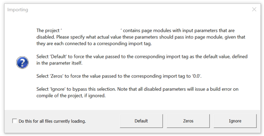
Disabled Module Parameters:The disabling module parameters is a serious business, as they are connected directly as inputs to actual circuits, drawn within the module schematic. If a disabled parameter is connected to an import tag on the schematic, which is likely an input to a controller or similar, what value should be passed into the import tag? The answer is important, as it can affect the accuracy simulation results. When a project is imported into PSCAD v5.1.0 and greater, it is scanned for disabled module parameters. If encountered, the following dialog is presented on a per project basis. Please take care in selecting one of the three options provided.
New Binary EMTDC Output File Format: A brand new EMTDC output file format (*.psout) is included with the PSCAD V5 release. A proprietary design, this new format is binary, which ensures a much smaller storage footprint, as well as faster data access. Not only does it store all simulation curve and trace data, but it can also store all sequential or parallel multiple run data, as well as animated graphics information, all in a single file. As binary formats cannot be viewed in a text editor, a new utility, called the PSOUT Reader is also included with V5.
Unit Converter is Always Enabled: Unit conversion was first introduced in PSCAD V3. At the time of its implementation, compatibility with legacy projects was an issue, so a project setting was introduced to allow unit conversion to be disabled. This option has been removed in PSCAD V5, and henceforth unit conversion is always enabled (starting with v5.0.0). If you are importing older projects that have the unit converter disabled, you will need to verify component input parameter units prior to running, as simulation results may differ.
Fortran Compiler Support: Support for v4.2.1 to v4.62 of the free GFortran 95 compiler has been dropped; v8.1 and v13.2 have been added. Support for the Intel Visual Fortran compiler versions 9 to 12.0 has been dropped; versions 12.1 to oneAPI 2025 have been added. See Supported Fortran Compilers for more details.
Smart Paste: Cut/copy and paste just got a whole lot smarter in PSCAD V5. Now when an object is copied, PSCAD stores a great deal more information on the Windows clipboard, so that when it comes time to paste, an intelligent decision can be made, depending on the context of the where the object is being pasted. This changes for the better, many familiar functionalities in PSCAD. See Smart Paste for details.
SCons Replaces Legacy Make/NMake Build System: The legacy make/nmake command-line interface tool, which has been used by PSCAD since its inception to provide build instructions for the associated Fortran compiler (via the generation of a configuration file called a make file), has been replaced with the more modern, python-based tool called SCons (https://scons.org/).
New Look and Feel: You will notice a brand new look and feel of the PSCAD application. We hope you find it pleasing.
There are other important issues to consider both before and after importing older projects into PSCAD V5. For more details on this, please see Importing PSCAD X4 Projects to V5.
The following is a general overview (non exhaustive) of new and enhanced features to be aware of:
Automation (Embedded Python Scripting): PSCAD is now fully automatable. Although the ability to control the application through Python script was introduced in PSCAD X4 (v4.6.1), it is now embedded in the software with its own scripting pane. In addition, users can now record their actions to generate script automatically. See Scripts and Script Output Panes for more details.
C-Coder: PSCAD may now be used to generate a fully formed, ANSI-standard, C language program, which may be run independently of EMTDC. The resulting code can then be used to program micro-controllers, etc. C-language program generation is accomplished by constructing a control circuit using a collection of our more basic, master library components, specifically from the Control System Modelling Functions (CSMF) section. Once constructed inside of an encapsulating page module, the C-language program is generated with a single click. Right-click and select Generate | Independent C-Code.
Parallel Multiple Run (PMR): The PMR feature enables users to launch multiple simulation runs in parallel, based on a single case project, but providing different data to each parallel simulation task. Each simulation is run independently on its own, unique processor core. See Parallel Multiple Run (PMR) for more details. As of PSCAD v5.1.0, it is also possible to simultaneously run a PMR of a Parallel Network Interface (PNI) simulation.
Automatic Page Module Creation from a Selection: Users may now collapse any selection of schematic components directly into a page module. Simply select one or more components, using any of the available selection methods, right-click and select Generate | Module (see Collapsing a Selection into a Module). The algorithm will consider both hard-wired and wireless signals that cross the selection boundary. Wireless signals include both those from data and node labels from/to output/input parameters, as well as #OUTPUT directive signals, generated within components, that are passed out via text parameters. If necessary, new parameters will be added to the generated module component to accommodate any wireless signals.
Multiple Language Support in Sticky Notes (Unicode): The PSCAD V5 code base has been updated to fully support Unicode, which enables users to use all known writing systems within sticky notes.
Communication Fabric (ComFab): A new inter-application communications control architecture, referred to as the Communication Fabric (or ComFab for short), is included with V5. ComFab is a separate layer that acts as a middle-ware for communications between processes. It is generic enough to be expandable and can be utilised by third-party software to communicate with PSCAD and EMTDC, provided that protocol is adhered to.
Component Templates: Pre-configured collections of components and modules may now be consolidated and stored as a Template object. Functional in both library (*.pslx) and case (*.pscx) projects, simply select a group of components on the schematic canvas, right-click and select Generate | Template.
Co-Simulation Interface: A general Application Programming Interface (API, enabling EMTDC to link to, and co-simulate with, just about any external application is included in PSCAD V5. Referred to as the Co-Simulation API, it is in it’s basic form, a C-language structure called EmtdcCosimulation_Channel, which houses a collection C-language functions. These functions can be used to customise an interface on the external application side. At the same time, a new master library component called Cosimulation, may be utilized in a case project to quickly provide the PSCAD/EMTDC side of the interface.
Cluster Launch System (CLS): The Cluster Launch System (CLS) is a utility used by PSCAD to launch simulation processes on remote computers. Running processes across multiple computers requires additional software to manage the simulation processes. Enter the CLS, a utility that can both launch and manage simulations on a computational cluster.
Blackboxing Electric Networks: Electric networks are now supported in blackbox. Starting from the top-level page module, an entire electric network (including control systems), which may span across several module levels, can be collapsed into a single component, complete with multiple instance compatible, Fortran source code. The new blackboxing algorithm is more powerful and robust than previous versions. For more details, see Blackboxing Modules.
Transmission Lines in Blackbox: Overhead transmission lines and underground cables are now supported when blackboxing modules. Utilizing a brand-new definition script segment called Subsystems, users may include transmission systems within a module to be blackboxed, provided both ends of each line exist within the same module. The presence of transmission lines also means that multiple, electrical subsystems are now supported for the first time, within non-module components. For more details, see Blackboxing Modules.
Improved Component Parameter Editor: The parameter editor, part of the component definition design editor, is completely refactored in PSCAD V5. The original parameter editor, included as part of the V3 and V4.1/V4.2, was updated to a brand new, windows forms-based editor for the entire X4 product series (v4.3 to v4.6).
This same editor looks similar in V5 after the update, but has been reorganised so as to display the parameter dialog dynamically, while it is being edited. This enables the user to see exactly what the dialog will look like, without the need to exit the editor, or press the Test Dialog button (the Test Dialog is still necessary for actual functionality testing, however). Also, much of the underlying functionalities have been improved and cleaned up, resulting in a more intuitive and efficient work environment.
It is now possible to control the visibility of an individual component parameter, based on a conditional statement, in addition to the existing enable/disable control. This is facilitated via a new parameter attribute called Visibility.
Enhanced Component Parameter Dialog: In an effort to provide a more efficient means of organising very large amounts of component input and output parameter data, the component parameter dialog has been greatly improved for the V5 release. Two huge improvements were made: The manner in which parameter category pages are organised, as well as the inclusion of a Java-based, dynamic display and feedback window, called the Dynamic Help Window.
The flat, drop-list category page format, which has been a part of PSCAD since the V2 days of the 1990s, has been replaced by a multi-level, tree-based category window. The new tree style can be extended to provide multiple branch levels (branches within branches), to provide a second dimension to the organisation of categories.
A very powerful and customisation display window, called the Dynamic Help Window, is also included in the new parameter dialog. The new pane is simply a viewing mechanism to display the output of an associated, Java-powered, HTML file. The power and flexibility of Java and its libraries may be utilised to create a wide assortment of parameter data visualisations, from help text, to images and dynamic graphs that change as the data changes.
Improved Component Wizard: A revamped component wizard has been included in this release, which possesses a much more flexible and feature-rich interface. New components (regular and module), transmission lines and cables may still be created from this utility, as before.
Enhanced Parameter Grid Pane: The immensely popular parameter grid feature has been completely re-architected in PSCAD V5, specifically to address the user-identified shortcomings of its predecessor in v4.6. For the most part, the new parameter grid looks and feels like the old one. However, under the hood we have made many changes that will facilitate functionality that was missing previously. Here is a list of some the more significant enhancements:
Support for buses, transmission lines and cables, simulation sets, file reference components and sticky notes: Virtually all schematic objects.
Results may be filtered by parameter category page, in addition to by page module.
Disabled parameters (instance-based) are now displayed as such in the parameter grid results.
Store, append and replace parameter grid results to/from file in *.cvs format.
Parameter grid results may be transferred directly to a spreadsheet, modified and then transferred back via copy/paste.
Full undo/redo support.
Global Substitutions: The global substitutions feature, part of the PSCAD X4 family of products (v4.3 to v4.6), has been completely redesigned for V5. Based on feedback from users over several years, we have assembled an entirely new global substitutions functionality, much more flexible and intuitive than the previous design. Major changes include:
A new global substitutions pane, which provides a central area to edit, add and delete all global substitutions related to a single project.
Inclusion of alternate global substitution values (or sets of values) when running the project as a task, in the context of one or more simulation sets.
Store, append and replace global substitutions to/from file in *.cvs format.
Set the min/max limits of slider components.
Custom Layer Configurations: Custom layer configurations enables internal customisation of a layer, by controlling the state of individual components within the layer.
Previous Run Playback: Previous Run Playback enables a replay of a previously run simulation, where the output results have been written in *.psout format (i.e. Save Channels to Disk? Is set to Advanced (*.psout)).
The following table comprises a list of all new models added to the master library since the PSCAD v4.2.1b release in 2007.
|
Graphic |
Name |
|
|
|
|
|
|
|
|
|
|
|
|
|
|
|
|
|
|
|
|
|
|
|
|
|
|
|
|
|
|
 |
|
 |
|
|
|
|
|
|
|
|
|
|
|
|
|
|
|
|
|
|
|
|
|
|
|
|
|
|
|
|
|
|
|
|
|
|
|
|
|
|
|
|
| Moving Average Filter | |
| PI Section (Single and Three-Phase) | |
 |
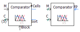
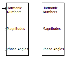
Frequency/Phase/Magnitude Meter |
 |
PID Controller |
 |
Hysteresis Controller |
|
|
|
|
|
|
|
|
|
|
|
|
|
|
|
|
|
|
|
|
|
|
|
|
|
|
|
|
|
|
|
|
|
|
|
|
|
|
|
|
|
|
|
|
|
|
|
|
|
|
The following is a general overview (non exhaustive) of new and enhanced functions to be aware of:
Subsystems Solved in Parallel: Subsystem solving is now multi-threaded, meaning several subsystems are solved simultaneously on different threads, enhancing simulation speed of multi-subsystem projects.
Improved Ideal Branch and Transformer Processing: Ideal branch and transformer processing is now improved by utilizing cached memory for some of the computations, enhancing simulation speed. A speed improvement is specifically noticeable in projects that contain many ideal branches and/or transformers.
GPU Sparse Algorithm Enabled for EMTDC: EMTDC may now utilise GPU processing power via an alternative sparse algorithm, in addition to the legacy sparse algorithm already inherent to EMTDC. To enable this feature, simply toggle the associated project setting.
Mutually Coupled Three Wires: The Mutually Coupled Three Wires component has been updated to provide the ability to model a zero-impedance transmission line. This is helpful when importing models from power flow software.
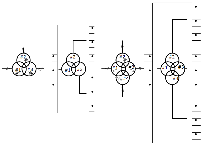
MoM-SO Method Added: Users may now opt to use MoM-SO methodology, instead of the classical formulas, to more accurately solve cable constants where proximity effects in the conductors are prominent. MoM-SO is a semi-analytical method used to compute cable parameters more broadly, considering proximity effects for the correct prediction of electromagnetic transients in cables that are placed close to one another, such as submarine cables.
Passivity enforcement of transmission lines and cables, based on constrained optimisation via spectral residue perturbation of propagation function, has been implemented.
It is now possible to model overhead towers and cables (aerial or underground) in the same cable model, with mutual coupling between them.
Extended earth return formula for aerial cables (calculates via efficient quadratic integration algorithm – Ametani/Liu). The aim is improved accuracy for GIS studies (frequencies up to 10 or 100 MHz, whereas the older formula is accurate up to only 1 MHz). More importantly this improves numerical stability of short, aerial GIS pipes. This algorithm calculates frequency-dependent ground impedance, as well as ground admittance.
Extended earth return formula for underground cables (Ametani). This improves the accuracy and stability of short cables. This algorithm calculates frequency-dependent ground impedance, as well as ground admittance.
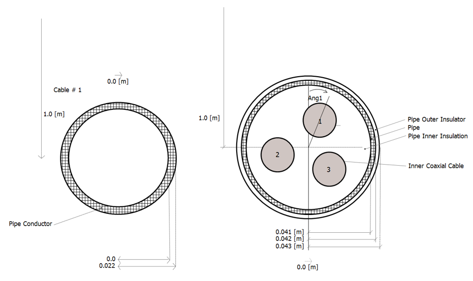
Accurate cable insulation loss representation, using loss factor for cables (including pipe-type cables), where the loss is modeled as a property of the insulation material. The cable shunt conductance is now obsolete (shunt conductance is also not valid in pipe-type cables, due to the shape of the inner insulation). In earlier versions, there was an ill-condition in calculating parameters at very low frequencies in the absence of insulation resistance. Hence, the DC Correction algorithm could not be applied to pipe-type cables.
Cable algorithm now can handle large cable systems of more than 12 cables in parallel.