 Workspace Branch
 Projects Branch
 Library Project
 Case Project
 Simulation Sets Branch
 Simulation Set
 Simulation Task
The primary window is used mainly for inter-project navigation, viewing project related data files and organization of simulation sets. Icons are included for visual differentiation between case and library projects. The main icons used here are listed below:
Workspace Branch
Projects Branch
Library Project
Case Project
Simulation Sets Branch
Simulation Set
Simulation Task
When a case or library project is loaded, the project namespace and description will appear by default in the primary workspace window, under the Projects Branch. It is of course possible to load multiple projects, and these will be listed in the order in which they are loaded. Each Project in the Projects Branch includes two additional branches to house data specific to that project: These are the Definitions and the Temporary Folder branches.
See Operations and Feature Overview for more on creating, loading and saving projects.
The definitions branch contains a list of all definitions that are stored locally within that project: Definitions for component, transmission segment or module instances that exist in a project, but are stored in other projects (ex. master library components), will not appear in this local definitions branch.
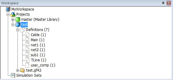
The image below shows the list of definitions for a case project called test. In addition to four module definitions, there is also one transmission line and one cable definition, as well as a component definition (called user_comp). The number in parenthesis affixed to the definition name indicates the total number of local instances of this definition in the project.
NOTE: It is not recommended to store user-defined component definitions within case projects. All component definitions should exist exclusively in library projects to avoid having to maintain multiple versions of the same definition.
The main icons used here are listed below:
 Component Definition
 Module Definition
 Transmission Line Definition
 Cable Definition
Right-clicking directly over the definitions branch will bring up a menu as shown below:
The following list describes the functions of this pop-up menu:
Component Wizard: This menu item will display the Component Wizard pane if not already displayed. The Component Wizard is used to create a Module, Component, TLine or Cable definition.
Import:
Definition(s)...: This function is used to import stored definition files (*.psdx or the older *.cmp format). See Importing/Exporting Definitions in the next chapter for more details.
From File (*.csv): Transmission line and cable definitions that have been exported to Comma Separated Variable (*.csv) format, may be imported by using this function. See Importing/Exporting Definitions for more details.
Paste: This function may be used to paste a definition that has been copied from this project or from another project loaded in the workspace primary window (see the Copy menu function described directly below).
Sort by Name: Select this option to sort the definitions list by name (see below). Continually selecting this option will toggle the alphabetical order from A to Z or Z to A.
Sort by Description: Select this option to sort the definitions list by description (see below). Continually selecting this option will toggle the alphabetical order from A to Z or Z to A.
If you right-click with the mouse pointer over a specific definition in the list, the following menu will appear:
The following list describes the functions of this pop-up menu:
Edit Properties...: This brings up the Definition Settings dialog window for editing the definition Name, Description and Lable(s). See Editing Definition Properties for more details.
Edit...: Select this option to edit the definition of the component (opens the Graphic window for components, or the Schematic window for modules, transmission lines and cables). See Editing a Component or Module Definition for more details.
Delete: Select this option to delete the definition. You will be prompted whether to delete the definition as well as all existing instances (select Yes), to delete only the definition (select No), or to cancel the action (select Cancel).
Copy: Select this option to copy a definition, which may then be pasted (see Paste, above), then instantiated (see Create Instance, below).
Create Instance: Select this option to create an instance of the definition. Note that once this option has been selected, go to a blank part of the Schematic canvas, right-click and select Paste. This will paste the newly created instance directly onto the page. Once the first instance has been created, subsequent copies may be made by directly copying the original instance. Holding down the Ctrl key and using Drag and Drop will also perform this feature.
Find Instances: Selecting this option will perform a project search of all instances linked to the selected definition. The results are displayed in the Search Results pane.
Export As...: This option brings up the Save Definition As dialog so that you can save the definition to a PSCAD Definition File (*.psdx). See Importing/Exporting Definitions for more details.
Help: If the definition is a component, selecting this option will open the associated help file (if one exists).
Module Definitions Only:
Copy with Dependents: Select this option to copy this definition and all of its dependents. This means that if this is a module definition, and it contains other modules as part of its definition, then these other modules will be included in the copy. See Copying and Transferring Module Hierarchies for more details.
Export with Dependents: All dependent modules definitions will also be included in the PSCAD Definition File (*.psdx) generated. See Importing/Exporting Definitions for more details.
Compile: Selecting this option will compile only the module selected. All module instances linked to this definition will of course be affected.
Transmission Line or Cable Definitions Only:
A double-click on a module definition will bring you directly to its definition canvas, whereas double-clicking on a component definition will bring you directly to its definition in the Graphic view. Double-clicking on a transmission line or cable will bring you to the definition Editor canvas.
Runtime related objects, such as Output Channels, Controls, Graphs, etc., help define the definition of the module, and are therefore organized under specific definitions in the definition tree. Module definition branches may be expanded to display a Schematic branch, which in turn may be expanded to display a list of all runtime objects, as well as transmission lines and cables. Whenever a runtime object is added, a record of it is immediately added under the appropriate module definition in the workspace.
As an example, the image below is taken from the Rectifier module in the Cigre Benchmark example case that comes with PSCAD.
Runtime objects can be categorized into several main groups:
Controls
Recorders
Display Devices
Named Signals
Radio Links
TLines/Cables
If you right-click with the mouse pointer over a specific object in the list, the following menu will appear:
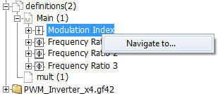
A left double-click on any runtime object in the list will highlight that object directly in the corresponding module definition canvas. For example, double-clicking on the Modulation Index object in the above diagram will result in the following in Schematic view:
![]()
This may also be achieved by right-clicking on a module listing and selecting Navigate To....
Icons are included in this branch for visual distinctness:
Controls:
![]() Slider Component Instance
Slider Component Instance
![]() Two State Switch Component Instance
Two State Switch Component Instance
![]() Dial
Component Instance
Dial
Component Instance
![]() Push
Button Component Instance
Push
Button Component Instance
Recorders:
![]() Output Channel Instance
Output Channel Instance
![]() RTP/COMTRADE Recorder Component
Instance
RTP/COMTRADE Recorder Component
Instance
Display Devices:
![]() Control
Panel Instance
Control
Panel Instance
 Plot
Frame Instance
Plot
Frame Instance
![]() XY
Plot Instance
XY
Plot Instance
 PolyMeter
Instance
PolyMeter
Instance
![]() PhasorMeter
Instance
PhasorMeter
Instance
![]() Oscilloscope
Instance
Oscilloscope
Instance
Named Signals:
![]() Data
signal defined with a Data Label
Data
signal defined with a Data Label
Radio Links:
TLines/Cables:
Transmission Lines and Cables
Transmission segment wires are themselves very similar to modules. As such, they are treated like a module instance when they are placed in the circuit.
If the line is an overhead line with Termination Style in Remote Ends mode, then a [+] box will appear beside the branch name. Expanding this branch (press the [+] symbol) will show the two interface components representing both ends of the transmission line. Note that cables will always have remote ends, as direct connection mode cables are not supported.
TLine/Cable Interface Components:
![]() Remote
End Interface Component Instance
Remote
End Interface Component Instance
Observers
Output channels and control objects can exist in a project without being associated with a curve, meter or control interface (i.e. the data is not plotted or monitored). If any of these objects are added as a curve to a graph, meter to a control panel, or added directly to a PolyMeter, PhasorMeter or Oscilloscope, an entry referred to as an observer will be added as a sub-branch to the corresponding recorder or control branch. If the object is displayed in more than one display device, an observer will be added for each occurrence.
The figure below shows the existing controls and recorders in the Network #1 module definition for a test project. The module contains a slider component called Slider 1, a two-state switch component called Switch 1, as well as two output channels entitled Ea and Switch 1. Each object possesses an observer to indicate that the output of the objects is being sent to a display device.
A simple double-click on any observer will point you directly to that occurrence of the runtime object within the display device. For example, double-clicking on the Slider 1 observer in the above diagram will result in the following in Schematic view:
Icons are included for all observer types. These are listed below:
Recorders:
![]() Curve
Curve
![]() Meter
Meter
![]() PolyMeter
PolyMeter
![]() PhasorMeter
PhasorMeter
![]() Oscilloscope
Oscilloscope
Controls:
![]() Slider
Slider
![]() Dial
Dial
![]() Two
State Switch
Two
State Switch
![]() Push
Button
Push
Button
Group Name Based Sorting
If any of the runtime objects are part of a runtime group, then the group name will precede the object name. This automatically categorizes the objects according to group name:

In the above example, controls Slider 1 and Switch 1 have been given the group name Control Group, whereas output channels Ea and Switch 1 have been given the group name Output Channels. For more information, see Grouping of Runtime Objects.
The Temporary Folder Branch is used specifically for convenient access to files found in the project temporary folder, such as FORTRAN, Data, Output, etc. files.
NOTE: The files will only be visible if you compile the project first (see Compiling and Building a Project in the next chapter).
To view the contents of the temporary folders branch, left-click the [+] box beside the project name:
A simple double-click on any file will open that file in the main viewing area of the environment. Right-clicking on the file will invoke a pop-up menu:
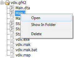
The functions in this menu are as described below:
Open: Open the selected file for viewing in the main window.
Show in Folder: Select this option to open Windows file explorer at the folder location where this file resides.
Delete: Delete the selected file from the temporary folder.
The master library is always the first project listed in the workspace primary window whenever PSCAD is started. It contains most of the components required to build almost any circuit. To open the master library, simply left-click the title in the workspace. The main master library canvas will open (Schematic window), giving access to all of its components.
Components stored in the master library are categorized into several modules (located on the main page), according to the functionality of the component. For example, all transformer components are stored in the Transformers module. In addition to these categories, most master library components are also located on the main page. Some users may find this format allows for easier navigation to the correct component.
NOTE: Component definitions stored in the master library can be viewed, but not directly modified. If you wish to modify one of these definitions, copy the definition into another library project and rename it first..
If you want to add any of these components to your own case, simply copy the instance directly from the master library and paste it into your own project. You can also use the Models tab on the ribbon control bar or the Library Pop-up Menu system.
It is possible to simultaneously launch and run multiple project simulations. Both sequential and parallel simulation runs are possible via the defining of Simulation Tasks within what are referred to as Simulation Sets. Only projects loaded under the Projects branch may be added as a task in a simulation set.
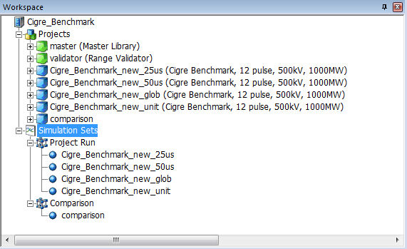
All simulations in a particular set will be launched simultaneously in parallel, utilizing all processor resources available on the local machine. All sets may be run sequentially: In the image above for example, if the user chooses to run all simulation sets, the set Project Run will launch and run all of its tasks in parallel. When these are complete, the simulation set Comparison will launch its tasks immediately after, and so on.
See Simulation Sets/Multiple EMTDC for more on creating and running simulation sets.