Ribbon
Schematic Canvas
Definitions Branch
New components (including modules and transmission segments) are created by using a utility called the Component Wizard. The Component Wizard generates a new definition, and then creates a single instance of it (by default) for placement on the Schematic canvas. The user may then continue with the design, given this basic new component.
The following topics describe the steps involved when navigating the Component Wizard. For more on component design, see the chapter entitled Component Design.
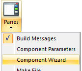
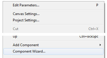
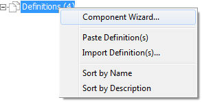
Open the Component Wizard pane by selecting either Component Wizard from the Panes drop list in the View tab of the ribbon control bar; or, move the mouse pointer over a blank area of any page, right-click and select Component Wizard; or, right-click on the definitions branch under the project node in the primary workspace window.
|
|
|
Ribbon |
Schematic Canvas |
Definitions Branch |
In either case, the Component Wizard pane will appear:
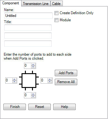
Enter all parameters required according to the descriptions below.
Name: Enter a name for the new component definition. This name must conform to Fortran standards (i.e. it cannot begin with a number or contain any spaces or other illegal characters).
Title (Optional): If text is detected in any of the three fields provided in this section, a text label containing the text will be added to the component graphic.
Module: Select this check box if you want the new component to be a module (also referred to as a page component or a sub-page).
Create Definition Only: Select this option to create the definition only, without attaching an instance to the mouse pointer.
Enter the required parameters required according to the descriptions below.
Click the Add Ports button after adding how many ports you will require at each side of the component graphic. Depending on what you selected, additional input fields will appear.
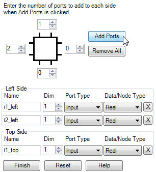
Name: Enter a Symbol name for the port connection. This name must conform to Fortran standards (i.e. it cannot begin with a number or contain any spaces or other illegal characters).
Dim: Enter a dimension for the port connection. Entering 0 indicates that this port is to assume the dimension of whatever it is connected to. Entering a 1 defines a scalar.
Port Type: Select the port connection type here. Note that for Input Data type, the Component Wizard will automatically draw an input arrow graphic for the port connection.
Node/Data Type: Select the type of electrical or data port connection here.
For more information on port connection types (i.e. electrical, data, etc.) see Port Connections.
Press the Finish button if you are satisfied that everything is correct. Press Reset to clear to defaults.