Radio Link components are a round-about means of creating a 'global variable' in PSCAD. The data is transmitted by inputting a data signal directly into a transmitter, which may then be 'received' at any location within the project by a receiver bearing the same name.
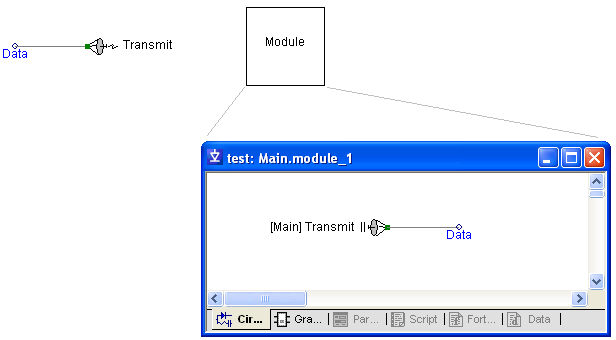
Radio Links circumvent the need to add external port connections (along with Import or Export components) to pass data signals between modules. As a matter of fact, Radio Links allow data signals to be transferred directly between multiple module levels. Although bidirectional transmission of data is allowed (i.e. either down or up multiple module levels), there are issues regarding time step delay that should be considered (see Time Step Delay Issues below for more).
Radio links may also be used to plot signal data without the use of an output channel, but only to plot end-of-run data, not during runtime. This is useful in the specific situation where you are running a master-slave simulation (see Root Control Interface). See the Robust Optimization workspace in the PSCAD examples folder for an example on this.
To plot the data from a radio link, either right-click the radio link and add it as a curve, or drag and drop it directly onto a graph. See Curves and Drag and Drop for more details on this.
Important Points to Remember:
Each global variable can be defined by only one distinct transmitter.
Transmitters cannot exist in multiple instance modules.
Each global variable can have 0 to n corresponding receivers.
All global variables are REAL numbers. If INTEGER signals need to be passed, then it is possible to convert the signal on either end with no loss of information.
Transmitters cannot be connected directly to output signals created by receivers.
More: |
Transferring Data Into and Out of Modules |