Special objects in PSCAD allow the user online access to input data signals, so that these signals (and hence the simulation results) can be altered during the course of the simulation run. These objects and how to use them are described in the following sections.
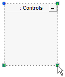
A Control Panel is a special component used for accommodating control or meter interfaces and can be placed anywhere on a Schematic canvas. Once a control panel has been added, you may then proceed to add as many control or meter interfaces to it as you wish.
Open the project in the Circuit view. Right-click on a blank portion of the page and select Add Component | Control Panel, or press the Control Panel button in Components tab of the ribbon control bar.
To move a control panel, move the mouse pointer over the title bar and then left-click and hold. Drag the frame to where it is to be placed and release the mouse button.
To re-size, move the mouse pointer over the title bar and left-click to select the panel. Grips should then appear around the outer edge as shown below.
Move the mouse pointer over one of the grips. Left-click and hold and then drag then move the pointer to re-size.
Right-click over the control panel title bar and select Cut or Copy respectively. You can also use the standard Ctrl + X or Ctrl + C shortcuts. Once a control panel has been cut or copied it may then be pasted into another location in the project (along with its contents).
Cut or copy a control panel as described above. Right-click over a blank area of the Schematic canvas and select Paste. A control panel may be pasted multiple times.
To access the Control Panel Settings dialog, left double-click the control panel title bar, or right-click over the title bar and select Control Panel Settings....
Presently the only adjustable panel property is the caption:
Caption: Enter a title for the control panel (this text will appear in the panel title bar). The default text may appear a bit cryptic: This syntax is used as a naming convention for grouping objects in the workspace.
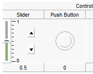
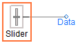
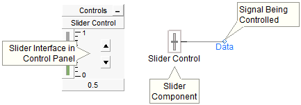
A Control Interface is a user interface object, which allows manual adjustment of input data signals dynamically. A control interface must first be linked with one of the runtime control objects available in the master library (i.e. Slider, Two State Switch, Rotary Switch, and Push Button). The control interface will then control the output of the linked control component. For example, the following image shows a slider component linked to a control interface in a control panel.
There are two methods to accomplish this:
Drag and Drop: Hold down the Ctrl key, left-click and hold the associated control component and drag and release over the control panel. See Drag and Drop for more details.
Right-click on the associated control component and select Graphs/Meters/Controls | Add as Control. Right-click over the desired control panel title bar and select Paste.
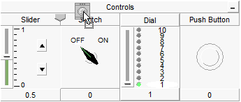
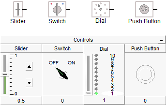
Of course, each type of control component will have a different control interface when added to a control panel. The following figure shows the available control components and their corresponding control interfaces:
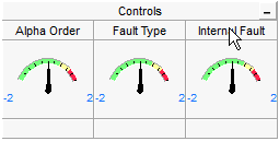
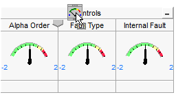
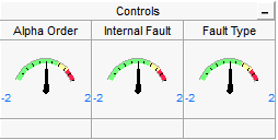
Once multiple control interfaces have been added to a particular panel, you may change the order in which they appear. This is accomplished by either using drag and drop, or the right-click menu:
Drag and Drop: Press Ctrl and then left-click and hold over the title bar of a particular control interface and then drag the mouse pointer over the control panel title bar. A downward arrow will appear between existing interfaces depending on the position of the mouse pointer. Release the left button to drop the interface.
|
|
|
Left-Click and Hold |
Drag |
Release Button |
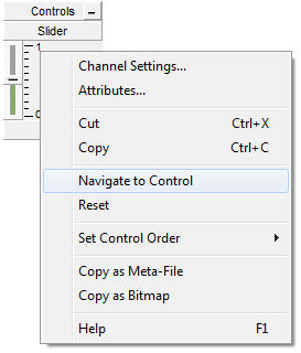
Right-click over the control interface and select Set Control Order. Choose one of the options given.
Right-click over the control interface title bar and select Cut or Copy respectively. Once a control interface has been cut or copied it may then be pasted into control panel in the project.
Cut or copy a control interface as described above. Right-click over a control panel title bar and select Paste. A control interface may be pasted multiple times.
You can navigate directly to the control component associated with a particular interface, by selecting this option. Right-click over the interface and select Navigate to Control. PSCAD will automatically find the associated output channel and highlight it.
|
|
Select Navigate to Control |
PSCAD Points to Object |
Control interface properties and the corresponding control component properties are one and the same. Therefore, you can either adjust these properties through the control component directly, or through the corresponding interface as follows: Left double-click the interface title bar, or right-click over the interface title bar and select Channel Settings....
Once a particular control interface has been added to a panel, the user may operate it manually, either before or during a simulation run. Of course, each type of interface will perform a different operation on its corresponding output signal.
Switch and Push Button Components:
To operate either the Switch or Push Button components, simply left-click over top on the control interface itself. For example, each time the switch interface is clicked it will toggle the corresponding switch component between its two output states.
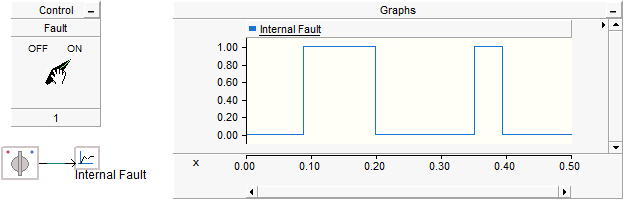
The image below shows a plot of a switch component output, where the user has changed its state (i.e. turned it on and off) during a 1.0 second simulation run.
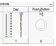
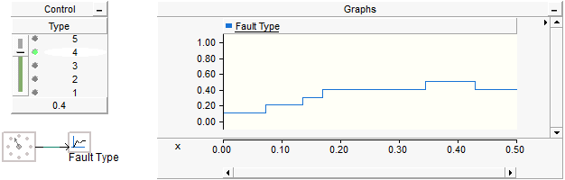
Dial Component:
To operate the Dial component, left-click and hold on the slider control knob and move the knob up or down. As the control knob is moved, the dial interface will indicate graphically, which of the multiple states is currently being output from the corresponding dial component.
The image below shows a plot of a dial component output, where the user has changed its state during a 1.0 second simulation run.
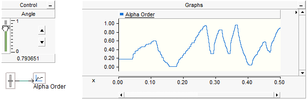
Slider Component:
The Slider component is operated in the same manner as the dial interface described above. The only difference is that the slider output does not operate in discrete states, but provides a continuously variable output.
The image below shows a plot of a slider component output, where the user has varied its output during a 1.0 second simulation run.
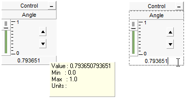
It is important to note that the Slider component will output exactly what is shown on the slider interface. The slider interface has a maximum precision of 6 significant digits. If more precision is required, you can add successive slider outputs together, each handling different data ranges. Once you have fine-tuned the slider output, you can replace it with a Real Constant component, which is capable of higher precision.
The slider interface also allows you to enter an exact value (up to 6 significant digits) directly into its display window. Simple left double-click on the display window and then enter the data. Press the Enter button to exit and save the entered data, or press Esc to exit without saving changes.
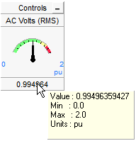
A meter is similar to a graph, in that it is used for displaying an output signal and is linked to a corresponding Output Channel. Instead of displaying the signal as a curve (as a graph would), the signal is used to operate a realistic meter display, with a pointer position proportional to the signal magnitude. For example, the following image shows an output channel component linked to a meter in a control panel.
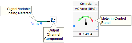
Meters can exist only within a control panel.
Like a control interface, meter interfaces display a maximum of 6 significant digits. However, twelve significant digits can be viewed via the tool tip.
There are a couple of methods to accomplish this:
Drag and Drop: Hold down the Ctrl key, left-click and hold the associated Output Channel component and drag and release over the control panel. See Drag and Drop for more details.
Right-click on the associated output channel component and select Graphs/Meters/Controls | Add as Meter. Right-click on the desired control panel title bar and select Paste.
Once multiple meter interfaces have been added to a particular control panel, you may change the order in which they appear.
Drag and Drop: Press Ctrl and then left-click and hold over the title bar of a particular meter interface and then drag the mouse pointer over the control panel title bar. A downward arrow will appear between existing interfaces depending on the position of the mouse pointer. Release the left button to drop the interface.
|
|
|
Left-Click and Hold |
Drag |
Release Button |
Right-click over the meter interface and select Set Control Order. Choose one of the options given.
Right-click over the meter title bar and select Cut or Copy respectively. Once a meter has been cut or copied it may then be pasted into any control panel in the project.
Cut or copy a meter as described above. Right-click over a control panel title bar and select Paste. A meter may be pasted multiple times.
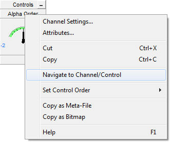
You can navigate directly to the Output Channel or I/O control component associated with a particular meter interface, by selecting this option. Right-click over the meter interface title bar and select Navigate to Channel/Control. PSCAD will automatically find the associated output channel or I/O control component and highlight it.
|
|
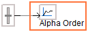
Select Navigate to Channel/Control |
PSCAD Points to Object |
Meter properties and the corresponding Output Channel parameters are one and the same. Therefore, you can either adjust these properties through the output channel directly, or through the meter as follows: Left double-click the meter title bar, or right-click over the title bar and select Channel Settings....