Input Field Property Settings for Vset & Vbase
There are several segment types available. Each exists for a specific purpose, but are only required if that specific function is needed as part of the component design. Most of the time, a definition will only require two or three of segments.
NOTE: Although this section does provide an assortment of simple examples, there is a huge wealth of examples in the master library project itself. Simply edit any master library definition (right-click on the component and select Edit Definition...) to study its contents.
The Computations segment is an environment provided for the pre-processing of component input data, as well as creating new internal variables. Although component parameter input may be in the most convenient form for the user, it may not be so convenient for the definition itself. For example, the definition may require the system frequency in radians per second, but the input data field may ask the user for the same quantity in Hertz.
The Computations segment is the first segment considered by the compiler when the component is compiled. Due to this fact, any quantities defined here may be substituted elsewhere in any of the other segments. This segment allows both mathematical and logical expression evaluation.
NOTE: All script processed within the Computations segment is done so before any Fortran code is constructed for EMTDC, and only considered once. Therefore, quantities defined here are static for the remainder of the simulation.
A typical Computations segment entry must have the following standard format:
<DataType> <Name> = <Expression>
Where,
<DataType> may be either a REAL or INTEGER type value. If omitted, it is assumed to be REAL
<Name> is the name of the constant
<Expression> is a mathematical or logical expression containing only constant parameters
EXAMPLE 9-3:
A designer wants to convert an input parameter with symbol name Vset in kV, to a per-unit value called SetPU, before it is used in component Fortran code. An additional input parameter with symbol name Vbase in kV has also been defined for the system voltage base.
|
Input Field Property Settings for Vset & Vbase |
The Computations segment could then contain something similar to the following:
REAL SetPU = Vset / Vbase |
In the above example, the designer has defined a new REAL constant entitled SetPU. This constant may now be used in any other segment in the Script section, both in equations and/or in logical expressions.
The Branch segment is primarily for the provision electric branch information to the EMTDC Electric Network Conductance Matrix: It is essentially an input portal for control of the EMTDC Equivalent Conductance (GEQ) Interface. Branch design is accomplished by specifying the type and size of passive elements (i.e. lumped R, L and/or C), and to which electrical port connections they fall between.
A single Branch statement represents a single electrical branch, to which is associated an impedance Z = R + jX, where Z is derived from a combination of series-connected, lumped R, L and/or C values. The Branch segment may also be used to define switching branches and those that contain an ideal voltage source (i.e. infinite bus).
A typical Branch Segment entry must have the following standard format:
[<Branchname> = ] $<TO> $<FROM> [<Keyword>] [$]<R> [$][<L>] [$][<C>]
Where,
<TO> and <FROM> are the symbol names of the electrical port connections defined in the Graphic section
<R> is the resistance value of the branch [W]
<L> is the inductance of the branch (optional) [H]
<C> is the capacitance of the branch (optional) [mF]
<Branchname> = may be used to give the branch a name, which can be used to refer to the branch (instead of its nodes) in other sections. Note that many EMTDC subroutines require the branch name as an argument.
<Keyword> can be either SOURCE or BREAKER and is explained in the following sections
$ is the Substitution Prefix Operator ($)
NOTE: If a branch does not contain all three types of R, L and C elements, simply substitute 0.0 for the value of the element that is not present.
A designer wants to define a component, which represents an RC series branch, connected in parallel with a purely inductive branch, between electrical port connections N1 and N2. These two port connections have already been defined in the Graphic section of the definition.
|
Component Graphic with Electrical Connections N1 and N2 |
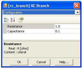
The actual values of the R and C elements are to be entered though input fields (with symbol names R and C respectively) in the Parameters section of the definition. The inductance value is not accessible to the user and is given a static value of 0.001 H directly.
|
Component Parameters Dialog |
The Branch segment would then contain the following two statements:
$N2 $N1 $R 0.0 $C $N2 $N1 0.0 0.001 0.0 |
These statements are equivalent to the following schematic:
The designer then decides to refer to the branches by branch name in other sections of the definition. To achieve this, the names BRN1 and BRN2 are defined. The designer modifies the above branch statements as follows:
BRN1 = $N2 $N1 $R 0.0 $C BRN2 = $N2 $N1 0.0 0.001 0.0 |
NOTE: If BRN1 and BRN2 are used in other segments, they must be preceded by the Substitution Prefix Operator ($).
The branch may also contain an inherent ideal source in series with the passive elements. The Branch segment syntax allows you to indicate to the application that there is a voltage source in a particular branch as follows:
[<Branchname> = ] $<TO> $<FROM> SOURCE [$]<R> [$][<L>] [$][<C>]
Now that PSCAD knows that there is a source in this branch, control of the source (i.e. magnitude, etc.) is then up to the user. One way this can be accomplished is by defining the EMTDC internal variable EBR every time step, directly in the model code itself.
NOTE: For more examples on this, edit the definition of the Voltage Source Model 2 in the master library project.
EXAMPLE 9-5:
A designer adds a resistive branch containing an ideal voltage source to the component in Example 9-4, which is to be connected between node N1 and a ground electrical port connection GND. The source possesses a source resistance RS, which can be entered as an input parameter.
The Branch segment could then contain something similar to the following:
BRNS = $N1 $GND SOURCE $RS 0.0 0.0 BRN1 = $N2 $N1 $R 0.0 $C BRN2 = $N2 $N1 0.0 0.001 0.0 |
These statements are a schematic equivalent to:
The Branch segment syntax also allows you to indicate to the application that a particular branch is a switching branch:
[<Branchname> = ] <TO> <FROM> BREAKER <Initial_Value>
Where,
<Initial_Value> is the initial resistance of the switch [W]. This value is used for initialization purposes and does not affect the simulation. A good default value to use is 1.0.
The Fortran segment is where any Fortran code, defining what the component is to model, is placed. Code entered in this segment should either exist in the form of standard Fortran 90, or Definition Script (or a combination of these two). It is also possible to define a function, or call an external subroutine from this segment.
When using actual Fortran code in this segment, it is important to note that all lines should be preceded by the allotted six spaces.
EXAMPLE 9-6:
The following code is a simple example of how standard Fortran would appear in the Fortran segment. This code defines an instantaneous voltage source magnitude VT, according to the value of an input parameter Type. If Type = 0, then the magnitude is calculated using the standard equation for a sinusoidal source with phase shift:
![]()
If Type = 1, then the source magnitude is a constant given by VDC. FREQ and PHI are also input parameters defined in the Parameters section of the definition. TWO_PI is an EMTDC internal constant.
! Calculation of an AC or DC voltage source magnitude ! --------------------------------------------------- ! !23456 Remember to precede code by at least six spaces! ! IF ( $TYPE .EQ. 0 ) THEN ! ! AC source ! $VT = $VPEAK*SIN( TWO_PI*$FREQ*TIME + $PHI ) ! ELSE ! ! DC source ! $VT = $VDC ! ENDIF ! |
This same code could also be written as a combination of standard Fortran and Definition Script as follows:
! Calculation of an AC or DC voltage source magnitude ! --------------------------------------------------- ! !23456 Remember to precede code by at least six spaces! ! #IF $Type == 0 ! ! AC source ! $VT = $VPEAK*SIN( TWO_PI*$FREQ*TIME + $PHI ) ! #ELSE ! ! DC source ! $VT = $VDC ! #ENDIF ! |
Note that the above two examples have been simplified slightly. Generally speaking, the value for the 2pft function should never be allowed to simply grow larger and larger as the simulation progresses. It should be reset to zero whenever 2pft = 2p is reached.
There are pros and cons to adding in-line Fortran code directly into the segment, as opposed to calling a subroutine or function. Here are some key points to consider:
All EMTDC Internal Variables may be utilized, without the need to declare them or add include files, when coding in the Fortran segment.
Definition Script may only be utilized when coding directly in the Fortran segment.
All code placed in the Fortran segment will be added directly to the module Fortran file (<module>.f), when the project is compiled. If there is a large amount of code and/or there are many instances of this definition in the module, the module Fortran file can become huge and difficult to debug. In such cases, it would be wise to create a function or subroutine, which could be simply called from the Fortran segment. Also, if Fortran line numbering is used in your code, these same number may appear multiple times in the Fortran file (<module>.f), causing compiler errors.
The Fortran segment is a 'smart' segment, in that code placed here will be intelligently placed in the EMTDC System Dynamics, in order to avoid problems with time step delays. In other words, PSCAD will choose to place the code in either the DSDYN or DSOUT subroutines, according to what variables are being defined in the code, and what this component is connected to in the project.
This segment is identical to the Fortran segment, except that all code will be forced into the DSDYN section of the EMTDC System Dynamics.
This segment is identical to the Fortran section, except that all code will be forced into the DSOUT section of the EMTDC System Dynamics.
The Checks segment is used to ensure that data entered into the component input parameters by the user is reasonable. If a specific condition is true, then a given warning or error message can be made to appear in the Build and Runtime Message Panes when the case is compiled.
A typical Checks segment entry would have the following standard format:
<MESSAGE TYPE> <Message> : <Expression>
<MESSAGE TYPE> is the first word in the message line and must be chosen as either WARNING or ERROR depending on the problem severity. If chosen as a warning, the message will appear as a warning in the Build and Runtime Message Panes. If specified as an error, then the simulation will be stopped until the condition is rectified.
<Message> is the diagnostic message that is printed if an error or warning is produced. This message should be descriptive enough for another user to determine what the problem is, and where it is coming from.
<Expression> is the test used to determine if an error or warning message should be generated. This expression is based on negative logic, which means the message is generated only if the expression evaluates to false.
EXAMPLE 9-7:
A designer's component contains an input for frequency with symbol name F. The designer wants to ensure that only a value greater than zero is entered.
The Checks segment should then contain the following:
ERROR System frequency must be greater than zero : F > 0.0 |
Both Logical and Arithmetic Operators may be used in the expression. For example:
WARNING R1 / R2 must be greater than 100 : R1 > 100*R2 |
Remember that negative logic is used in the above examples!
The Help segment is useful when the user wants to provide an external HTML based help file for a particular user-defined component. For example if the user has created an HTML document entitled help.html for example, then all that is required that the name and extension be added to the Help segment as shown below:
help.html |
When a user right clicks on the component instance and selects Help from the pop-up menu, the external document indicated will open.
Please note the following important facts:
Help File Placement: In order to reduce confusion when linking components to help documents, the path to the library project (*.pslx) file, in which the definition is located, will be appended to the filename. Therefore, the external help file must always be located in the same directory as the parent library project.
HTML Browser: You must choose an HTML browser program for viewing custom help files. This is accomplished through the HTML Browser workspace setting. See Application Options Dependencies category description for more.
Add your comments / reminders / notes about the design of this component here. Do not use this segment as a means of providing help to users. This segment is ignored by the application and is accessible only when editing the definition.
The FlyBy segment provides an avenue for the designer to apply fly-by (or pop-up) help to a component. Fly-by windows can help to provide users with a quick description of the model itself, or even individual port connections on the component.
The FlyBy segment syntax is straightforward:
<Descriptive text for the component>
: <Connection_Symbol_Name>
<Descriptive text for the connection>
EXAMPLE 9-8:
A designer wants to add fly-by help to the component below:
In addition to a general description of the component, the designer wants to provide a fly-by for each of the input port connections A and B.
The FlyBy segment should then contain something similar to the following:
This is my User Component :A This is input A :B This is input B |
If the mouse pointer is now moved over the component while on the Circuit canvas, the following fly-by windows will appear:
The Transformers segment is used both to define data for any existing mutual impedance matrices, as well as to provide dimensioning information to EMTDC regarding transformers and windings. A single component may contain multiple mutual impedance matrices.
The user must include transformer information in the following parts:
Number of transformers (matrices): This is entered via the use of a #TRANSFORMERS directive. See Definition Script for more details.
Maximum Number of Windings: This is entered via the use of a #WINDINGS directive. See Definition Script for more details.
Number of Windings: This number will define the dimension of each matrix. If this number is given as a positive value, then PSCAD will assume that the matrix is in non-inverted format, and therefore the matrix data must be entered directly. If the number is negative, it signifies that this transformer is 'ideal' (i.e. contains only inductance) and PSCAD will assume that the matrix is already inverted. The matrix data must therefore be entered accordingly.
Matrix Data: The matrix data is entered here, depending on whether the transformer is 'ideal' or not.
According to the above description, a basic Transformers segment would appear as follows (for a classical type transformer) in general format:
#TRANSFORMERS <Number_of_Transformers>
#WINDINGS <Number_of_Windings>
<Prefix><Number_of_Windings> /
<Node_1> <Node_2> <R_11> <L_11> /
<Node_2> <Node_3> <R_12> <L_12> <R_22> <L_22> /
...
NOTE: The Transformers segment format is different when defining a UMEC type transformer. For more information on the UMEC format, see the UMEC transformer component definitions in the master library, or contact the PSCAD Support Desk (support@pscad.com).
<Prefix> is not mandatory, but is required to indicate an 'ideal' transformer matrix (i.e. already inverted). Also, resistance values (i.e. <R_xx>) are not required if the transformer is 'ideal'.
Note that only the diagonal and the data below the diagonal need to be entered. The matrix is assumed to be symmetrical.
EXAMPLE 9-9:
A user wants to create a non-ideal, single-phase, two-winding transformer. The component Graphics, Parameters and other Script section has already been included. The component electrical port connections have been set-up as shown below in the Graphic section.
The winding self and mutual resistance and inductance parameters have been defined and given symbol names R11, L11, R12, L12, R22 and L22.
The Transformers segment should then appear similar to the following:
#TRANSFORMERS 1 #WINDINGS 2 ! 2 / $A1 $B1 $R11 $L11 / $A2 $B2 $R12 $L12 $R22 $L22 / ! |
When designing a component with more than one transformer, you can use a special syntax (called 888 syntax) so that, if all the matrix elements are identical, you can avoid entering the repetitive data. This is especially useful if the mutual impedance matrices are very large and numerous.
EXAMPLE 9-10:
In the example above, the user wants to modify the component, so that it contains two identical single-phase transformers within it. The component electrical port connections have been set-up as shown below in the Graphic section.
The Transformers segment should then appear similar to the following:
#TRANSFORMERS 2 #WINDINGS 2 ! 2 / $A1 $B1 $R11 $L11 / $A2 $B2 $R12 $L12 $R22 $L22 / ! 888 / ! $A3 $B3 / $A4 $B4 / |
The Model-Data segment is used as a way to bring input data into a user-defined subroutine, without having to declare an argument for each bit of data. There is no specific format for text in this segment, as this format depends on READ statements within the user code.
When the project is compiled, PSCAD will include all text in this segment within the corresponding module Data File (*.dta), under the headings DATADSD or DATADSO. If the subroutine is called from DSDYN, the Model-Data contents will appear in the DATADSD section; and DATADSO otherwise.
In order to read this information, a standard Fortran READ statement must be added to the user-defined subroutine as follows:
! ! Add include file to define IUNIT ! INCLUDE 'fnames.h' ! ! ... ! READ(IUNIT,*) ... ! |
When a project is initially compiled, PSCAD will construct a temporary logical matrix for the purpose of indicating how the electrical system is connected (i.e. how nodes and branches are put together). The Optimize Node Ordering algorithm in PSCAD then uses this information to optimize node placement in the actual system conductance matrix. However, only electrical nodes and branches, defined within the Branch segments of each component present in the system, are considered.
Any internal node connections defined in segments other than Branch will not be included in this matrix. Therefore, the logical matrix may have missing information, thereby reducing the effectiveness of the Optimize Node Ordering algorithm. The Matrix-Fill segment can be used to 'help' this algorithm by providing the omitted connection information for any internal component nodes.
The general format for a Matrix-Fill Segment statement would appear as follows:
<Node_1> <Node_2> <Node_3> <Node_4> ...
Where <Node_#> is the Symbol name of the port connection involved. All port connections in a single statement are assumed as connected to each other.
EXAMPLE 9-11:
A user creates a single-phase electrical circuit in PSCAD, which includes a classical transformer component connected as follows:
As can be seen above, there are 6 electrical nodes in this system, and therefore the system matrix will have dimension 6 x 6. Connections internal to the transformer component cannot be determined initially by PSCAD, and so when a logical matrix for the Optimize Node Ordering algorithm is created, the transformer appears as a 'black box' as shown below:
The logical matrix for the Optimize Node Ordering algorithm would appear as follows, where X indicates a known connection:
The matrix above does not contain all of the connection information required however. We know through the Transformers segment in the transformer component, that nodes N2, N3, N5 and N6 are all part of a mutual impedance matrix and are hence all connected together as shown below:
By adding in Matrix-Fill information, we can tell PSCAD to add connection information to the matrix so it will appear as follows, where '+' indicates a connection added by Matrix-Fill:
If the four electrical port connections on the transformer were given as follows in the Graphic section of the definition,
then the Matrix-Fill segment should appear as:
$A1 $B1 $A2 $B2 |
Note that in the above example, it assumed that all connections between the four nodes involved are possible. If however, only connections as shown below are needed,
then the Matrix-Fill segment should appear as:
$A1 $B2 $A2 $B1 |
The T-Lines segment is used to specify any electrical port connections that are to be used as sending or receiving end port connections for a transmission line or cable. The T-Lines segment is rarely needed in component design. The general format of statements in this segment is given below:
<Subsystem_#> <Cond_1> <Cond_2> <Cond_3> ...
<Cond_#> signifies that any port connection Symbol name that is entered in this position will be the sending or receiving end port connection for that particular conductor number in the transmission line or cable properties.
This Segment is used only within the Transmission Line and Cable Interface components in the master library.