Changing Port Connection Properties
Port Connections are used to provide graphical access to signals defined within the Circuit canvas where the component instance resides. They provide a means to either read signals from, or output signals to the external system each simulation time step. These ports play an essential part in the construction of circuits in PSCAD, and are the graphical signal communication avenue between models.
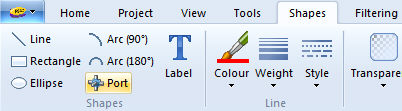
To add a Port Connection object to your component definition, the most straightforward method is to use the ribbon control bar Shapes tab:
Simply left-click the Port button on the ribbon bar, drag the connection to where you want it placed and left-click again. Another method is to use the right-click menu: Move the mouse pointer over a blank area of the Graphic window. Right-click and select New Graphic | Connection.
A port connection should appear attached to your mouse pointer. With your mouse, move the node to the desired location within the Graphic window and left-click to place the object.
NOTE: You may notice that port connections are always snapped to the Graphic canvas drawing grid. This is to ensure that when other components are connected to yours, their respective connection points will overlap.
Port connection properties can be adjusted through the Port Connection dialog. To change the connection properties: Either left double-click or right-click over the connection and select Properties....
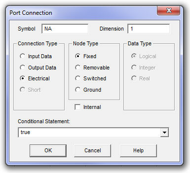
As shown above, connection features such as name and type can be adjusted.
Symbol: Enter a name for the port connection. Note that this name must be compatible with standard Fortran naming conventions (i.e. it must begin with a non-numeric character, must not include spaces or other illegal characters, etc.).
Dimension: If this connection is to carry an array signal, then this input specifies the dimension of the array. For example, if port connection N1 is to be defined as REAL N1(3), then this field should be specified as 3. You may also substitute the Symbol of an integer input field or choice list in this field. The connection will assume a dimension equal to this value upon compilation.
Connection Type: Select Input Data, Output Data or Electrical. If this connection is to be part of the EMTDC system dynamics (i.e. a control signal), then you must either choose Input or Output Data. Only select Electrical if this connection to be part of an electrical circuit.
Node Type: Select Fixed, Removable, Switched or Ground. This parameter is only enabled if the Connection Type is Electrical (see the following Electrical Node Types section). If designing a module component, only Fixed-type electrical nodes may be used.
Data Type: Select Logical, Integer or Real. This input defines the type of data signal that will be passing through this connection and is based on the standard Fortran LOGICAL, INTEGER or REAL declarations. It is only enabled if Connection Type is Input or Output Data.
Internal: Selecting this choice box simply disables the compiler warning message indicating that an internal electrical, isolated node exists. Note that this port can still be connected to other ports (via a wire, etc.) when flagged as internal.
Conditional Statement: Enter a conditional statement to determine under what input conditions the connection is to be enabled. See Conditional Statements, Layers & Filters for more details.
When the connection is selected as an electrical node, there are four electrical node types available to the user. These are described below:
Fixed: A fixed node is the most common type of electrical node and should be the default chosen when in doubt. It represents a simple electrical node.
Removable: A removable node is that which may be 'removed' by PSCAD, if it is to be part of a collapsible branch. For example, a branch with separate series RLC elements can be collapsed by PSCAD into an equivalent, single element impedance branch (Z) (effectively removing two extra nodes). Select removable if you would like to take advantage of this feature.
Switched: If your node is to be part of a frequently switching branch, that is a branch whose equivalent conductance is changing many times during a simulation (thyristor, GTO, etc.), then this option should be chosen. Switched nodes are included in the Optimal Node Ordering algorithm, which makes matrix decomposition more efficient, and thereby speeds up the simulation.
Ground: Select this option if your node is to be a ground node.
NOTE: Only Fixed-type electrical ports are allowed in module component definitions.