Adjusting Saturation Properties
The following topics discuss some attributes of the classical transformers in more detail.
All transformer components are equipped with an on-line tap changer. When the tap changer is enabled, a diagonal line will appear on the component graphic, labelled Tap.
A change in tap setting is modeled as a change in the turns-ratio of the transformer. The per-unit leakage reactance and magnetizing currents, specified for 100% tap, are used to calculate admittances for the new voltage rating, corresponding to the tap setting.
EXAMPLE 6-1:
Let us assume for simplicity, that a transformer is configured as Y-Y, with winding voltages rated at 10 kV primary and 100 kV secondary, and a tap changer is placed on the primary winding. The turns-ratio for this transformer is of course 1:10.
An on-line tap input of 1.0 corresponds to a 100% tap (i.e. no tap adjustment). If the tap input value is adjusted to say 1.05, then the turns-ratio would become 1.05:10 or 1:9.52381.
It is possible to have a continuous change of tap, but this would require a re-ordering of the network solution every time step. It is more practical to change tap settings in steps, either through manual adjustment, using a slider or rotary switch, or from a controller with appropriate delays and steps built in.
Saturation is represented in the classical transformer models with a compensating current source injection across the selected winding, based on a combination of measured winding voltage and component input parameters.
Properties of the classic core saturation method are described in this section.
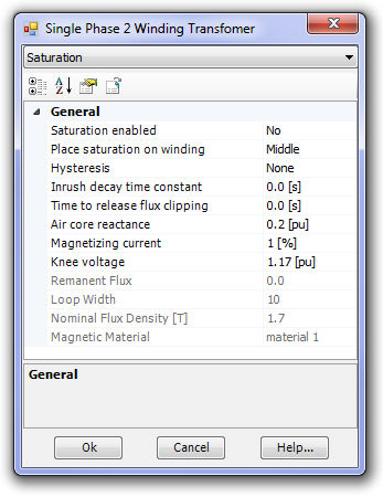
The transformer input parameters directly involved in the adjustment of the classic core saturation characteristic are:
Air Core Reactance
Magnetizing Current
Knee Voltage
These three parameters are shown, as they appear in the Saturation section of the component parameters in the figure above. Air core reactance, knee voltage and magnetizing current provide three degrees of freedom to the shaping of the continuous, core characteristic (knee curve) shown below.
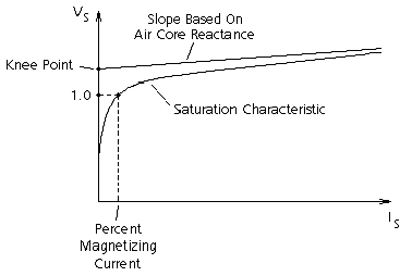
Figure 6-8 -- Typical Classic Core Saturation Characteristic
Adjustment of the air core reactance input affects the slope of the asymptotic line indicated in the above figure.
Adjustment of the Knee Voltage vertically shifts the Y-intercept of the air core reactance asymptotic line in the above figure.
Adjustment of the magnetizing current determines the horizontal position, along the VS = 1.0 pu voltage line, of the effective knee point. That is, an increasing value of magnetizing current will tend to make the saturation characteristic less sharp.