Common Intrinsic Network Variables
The intrinsic variables within EMTDC can be an essential part of interfacing user source. A good understanding of these variables is necessary to exploit the full potential from the tools available. The majority of EMTDC intrinsic variables are accessible to the user, and may be utilized within external source, provided that the proper header files are included. The following sections describe the most common variables: More detail is provided later in this chapter as well. If more information is required on intrinsic variables that are not discussed here, please contact the PSCAD support desk (support@pscad.com).
For a summary of which header file corresponds to a particular variable, see Include Files to Include later in this chapter.
Storage arrays are required in cases where variables need to be stored and made available in subsequent time steps, or when passing information from the BEGIN section of the system dynamics to DSDYN and/or DSOUT. The storage arrays are of single-dimension (sometimes referred to as a stack), where a different array exists for each variable type.
|
Type |
EMTDC Storage Array |
Description |
Inter Time Step Data Transfer |
REAL |
STORF(NSTORF) |
For floating point (REAL) storage only. |
INTEGER |
STORI(NSTORI) |
For INTEGER storage only. |
|
LOGICAL |
STORL(NSTORL) |
For LOGICAL storage only. |
|
COMPLEX |
STORC(NSTORC) |
For COMPLEX storage only. |
|
|
|
|
|
BEGIN to DSDYN/DSOUT Data Transfer |
REAL |
RTCF(NRTCF) |
For floating point (REAL) storage only. |
INTEGER |
RTCI(NRTCI) |
For INTEGER storage only. |
|
LOGICAL |
RTCL(NRTCL) |
For LOGICAL storage only. |
|
COMPLEX |
RTCC(NRTCC) |
For COMPLEX storage only. |
Table 5-1 - Available Storage Arrays and Pointers
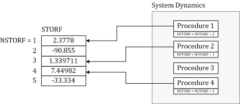
Figure 5-1 illustrates a typical storage array used in the transfer of data between time steps. Data may be stored at individual address locations, using the corresponding pointer integer (i.e. NSTORF, NSTORI, etc.). Proper use of the storage pointer is essential for accurate simulation results. If, for instance, the pointer is not properly addressed, data stored in previously called subroutines, may be over-written.

Figure 5-1 - Typical Storage Array (STORF) Usage by System Dynamics Procedures
Each time step, all storage array pointers are reset to one (1) and then the main program is sequenced from top to bottom. Using the storage array and pointer, each subroutine may write data to and read data from an array, consistent with the sequence in which the subroutine appears in the main program. In order to avoid stored data being over-written, each subroutine must increment the respective pointer, by the amount of storage locations used in the subroutine, before returning to the main program. This will ensure that the pointers are in their proper positions when the next storage access is performed.
Consider a user-written subroutine that requires that two variables be stored for retrieval in subsequent time steps: Two REAL variables X and Y and one INTEGER variable Z. The subroutine should include something similar to what is shown below:
! SUBROUTINE U_USERSUB(...) ! INCLUDE ′nd.h′ INCLUDE ′emtstor.h′ ! REAL X, Y, X_OLD, Y_OLD INTEGER Z, Z_OLD ! ! Retrieve the variables from storage arrays: ! X_OLD = STORF(NSTORF) Y_OLD = STORF(NSTORF + 1) Z_OLD = STORI(NSTORI) ! ! Main body of subroutine: ! ... ! ! Save the variables to storage arrays for use in next time step: ! STORF(NSTORF) = X STORF(NSTORF + 1) = Y STORI(NSTORI) = Z ! ! Increment the respective pointers before returning to the main ! program (very important): ! NSTORF = NSTORF + 2 NSTORI = NSTORI + 1 ! RETURN END ! |
Listing 5-1 – Illustration of STORx Array Usage
A good habit to get into is to make a copy of the storage pointer, and update the original one. The copy is used only in the local subroutine; therefore, if other nested functions or subroutines exist, storage pointer confusion is avoided. Using this approach, the above example would become:
! SUBROUTINE U_USERSUB(...) ! INCLUDE ′nd.h′ INCLUDE ′emtstor.h′ ! REAL X, Y, X_OLD, Y_OLD INTEGER MY_NSTORF, MY_NSTORI, Z, Z_OLD ! ! Copy the pointer values to locally declared variables: ! MY_NSTORF = NSTORF MY_NSTORI = NSTORI ! ! Increment the respective pointers before continuing: ! NSTORF = NSTORF + 2 NSTORI = NSTORI + 1 ! ! Retrieve the variables from storage arrays (using local pointers): ! X_OLD = STORF(MY_NSTORF) Y_OLD = STORF(MY_NSTORF + 1) Z_OLD = STORI(MY_NSTORI) ! ! Main body of subroutine: ! ... ! ! Save the variables to storage arrays for use in next time step: ! STORF(MY_NSTORF) = X STORF(MY_NSTORF + 1) = Y STORI(MY_NSTORI) = Z ! RETURN END ! |
Listing 5-2 – Illustration of STORx Array Usage with Local Pointers
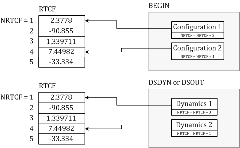
The BEGIN section is used to perform pre-run (or time zero) operations, such as initialization of variables, etc. Data transfer from BEGIN to both the DSDYN or DSOUT sections occurs at the beginning of each time step.

Figure 5-2 - Typical Storage Array Usage by BEGIN Procedures
BEGIN was introduced primarily to provide Runtime Configuration support in EMTDC when components exist within modules with multiple instances. The storage arrays used to transfer data (i.e. the RTCx arrays) are included, so as to not affect the storage operations of legacy user-components that were created using PSCAD versions previous to X4. All master library components use both storage array types when necessary.
To facilitate runtime configuration support (and thereby multiple instance modules support) within user-designed components, it may be necessary to utilize the BEGIN section (and hence the RTCx storage arrays). This is normally the case if the component requires time zero initialization.
EXAMPLE 5-2:
Consider a user-defined component that needs to store a set of two xy data points at time zero, for use later during runtime. The data points are defined as follows:
|
X |
Y |
Point 1 |
0.7 |
3.1 |
Point 2 |
1.2 |
3.8 |
Table 5-2 – Set of XY Data Points for This Example
The storage of these data points will need to occur within the BEGIN section of the system dynamics, so as to ensure that the component is Runtime Configurable. The user decides to write a subroutine entitled U_BGN_XYPOINTS that will be called within the BEGIN section. Note that the text BGN was added to the procedure name – this is to help identify it as BEGIN-type.
! SUBROUTINE U_BGN_XYPOINTS(X,Y) ! INCLUDE ′nd.h′ INCLUDE ′rtconfig.h′ ! REAL X(2), Y(2) ! ! Save variables to storage array for use in runtime: ! RTCF(NRTCF) = X(1) RTCF(NRTCF + 1) = Y(1) RTCF(NRTCF + 2) = X(2) RTCF(NRTCF + 3) = Y(2) ! ! Increment the pointers before returning to the main program ! (very important): ! NRTCF = NRTCF + 4 ! RETURN END ! |
Listing 5-3 – Illustration of RTCx Array Usage within BEGIN Subroutine
Now that the subroutine is defined, the user must specify to PSCAD that a call to it is to be inserted in the BEGIN section. This is accomplished by using the #BEGIN/#ENDBEGIN directives within the component definition. See Script Directives in the PSCAD manual chapter Definition Script if you are not familiar with these.
#BEGIN CALL U_BGN_XYPOINTS($X,$Y) #ENDBEGIN |
Listing 5-4 –BEGIN Subroutine Call from Component Definition
The $X and $Y variables represent pre-defined quantities in the component definition. These could be, for example, component input parameters. Note that instead of defining a subroutine, the data storage may also be coded directly in the component definition as follows:
#BEGIN RTCF(NRTCF) = $X(1) RTCF(NRTCF + 1) = $Y(1) RTCF(NRTCF + 2) = $X(2) RTCF(NRTCF + 3) = $Y(2) ! NRTCF = NRTCF + 4 #ENDBEGIN |
Listing 5-5 – Illustration of RTCx Array Usage within Component Definition
Now that the data is being stored in BEGIN, you will need to retrieve it during runtime. The user has written a subroutine that defines the runtime (or the dynamic modeling) operation of the component called U_DYN_XYPOINTS. This routine includes RTCx storage retrieval, along with STORx type arrays:
! SUBROUTINE U_DYN_XYPOINTS(...) ! INCLUDE ′nd.h′ INCLUDE ′emtstor.h′ INCLUDE ′rtconfig.h′ ! REAL X(2), Y(2) INTEGER MY_NSTORI, TEMP INTEGER MY_NRTCF ! ! Copy the pointer values to locally declared variables: ! MY_NSTORI = NSTORI MY_NRTCF = NRTCF ! ! Increment the respective pointers before continuing: ! NSTORI = NSTORI + 1 NRTCF = NRTCF + 4 ! Number of RTCF storage elements used ! ! Retrieve the variables from storage arrays (using local pointers): ! TEMP = STORI(MY_NSTORI) X(1) = RTCF(MY_NRTCF) Y(1) = RTCF(MY_NRTCF + 1) X(2) = RTCF(MY_NRTCF + 2) Y(2) = RTCF(MY_NRTCF + 3) ! ! Main body of subroutine: ! ... ! ! Save variables to storage arrays for use in next time step ! (STORx arrays only!): ! STORI(MY_NSTORI) = TEMP ! RETURN END ! |
Listing 5-6 – Illustration of RTCx Array Usage within DSDYN/DSOUT Subroutine
Through intrinsic variables, the user may access electric network data, such as branch and node numbers, as well as monitor branch current and node voltage. Some network variables, such as branch voltage may even be controlled.
NOTE: In the following tables, BRN and SS stand for branch number and subsystem number respectively. NN stands for node number.
Node numbers may be accessed as follows:
Variable Name |
Description |
IEF(BRN,SS) |
Gives the number of the mapped ‘from’ node |
IET(BRN,SS) |
Gives the number of the mapped ‘to’ node |
Table 5-3 – Intrinsic Variables to Access Node Numbers
The current flowing in a given branch can be monitored as follows:
Variable Name |
Description |
CBR(BRN,SS) |
Gives the value of current in a particular branch with the direction of positive current being from the ‘from’ node to the ‘to’ node. |
Table 5-4 – Intrinsic Variable to Access Branch Current
The voltage at a given node can be monitored as follows:
Variable Name |
Description |
VDC(NN,SS) |
Gives the value of voltage at node NN in subsystem SS. |
Table 5-5 – Intrinsic Variable to Access Node Voltage
These variables may be used for direct control of the electric network interface:
Variable Name |
Description |
EBR(BRN,SS) |
Sets the value of branch voltage |
CCBR(BRN,SS) |
Current source representing the history current when inductors and/or capacitors are used in an interface branch |
GEQ(BRN,SS) |
Sets the value of the branch equivalent conductance. |
CCIN(NN,SS) |
An ideal current source that sets the value of current injected into the node NN from ground. |
GGIN(NN,SS) |
Sets a conductance value between node NN and ground |
Table 5-6 – Intrinsic Variables for Control of an Interface to the Electric Network
NOTE: See the section entitled Interfacing to the Electric Network later in this chapter for more details.