Original Circuit
Sub-Circuit Consolidated into a Module and Connected to Greater Circuit
Data Signal Analogies to Fortran Code
Porting Data Signals by Port Connection
Porting Data Signals by Component Parameter
Porting Data Signals by Radio Links
At some point during project design, you may want to identify a common set of components, and consolidate them into their own module component. This procedure can be useful in simplifying and organizing the appearance of the overall project. It also helps to reduce duplication if the module can be multiple instanced. In doing this however, data signals and electrical nodes that once connected the module circuit to the greater circuit will sever, and these must be reconnected.
|
|
Original Circuit |
Sub-Circuit Consolidated into a Module and Connected to Greater Circuit |
The process of transporting data and connecting nodes between a module circuit and the greater circuit (i.e. its parent module), is referred to as porting. Porting signals and nodes between modules can be accomplished in a few different ways:
When a project is compiled, the application creates a variety of files describing the project, so that an executable file can be generated. Some of these are Fortran files (*.f), where one Fortran file is created for each unique module in the project (including the main page). Each file is a unique set of subroutines describing the content of the corresponding module.
When a data signal is passed into or out of a module, it will either appear as a subroutine argument (if it is ported as a parameter or port connection), or be transferred via storage array, inline within the subroutine code body, if using Radio Link components.
! SUBROUTINE DSDyn(X) ! . . .
|
Data Signal X as an Argument
! SUBROUTINE DSDyn() ! . . . X = STOF(ISTOF + 1)
|
Data Signal X Extracted from Storage Inline
If you create a new module component by using the Component Wizard, the process of adding port connections is fully automated. See Creating a New Component or Module later in this section for more details.
NOTE: Ported signal names are case sensitive. The port signal name must match its corresponding import/export tag exactly.
If you are editing an existing module, follow these general steps:
Edit the definition of the module. See Editing a Component or Module Definition in this section for more details.
Define an input or output port connection in the Graphic section (Graphic tab) of the module. See The Graphics Section for more details.
Add a corresponding Import or Export component on the module Schematic canvas. Each Import or Export must be named the same as its corresponding port connection.
EXAMPLE 5-1:
Consider a project that consists of a simple phase angle offset control being input into a module. The module Graphic section consists of a single port connection named in1, which is to be connected to the incoming data signal from its parent module. The input signal in1 is used as a reference angle to a firing pulse generator inside the module definition Schematic canvas.
|
|
|
Parent Canvas Containing Module Component and Greater Circuit |
Graphic View of Module Definition |
Schematic Canvas of Module |
A user wants to bring the firing pulse output signal back out to the main page using an output port connection. The first step is to define an Export component and connect it to the firing pulse output signal. The user names the export signal out. The final step is to define an output port connection in the module definition Graphic section.
|
|
Added Export tag in Canvas of Module |
New Output Port Connection in Graphic of Module |
The user may now input this new output signal to any other component on the main page.
|
Parent Canvas with Module and Controller with New Connection |
Note that only one instance of a uniquely named Import or Export component may exist within a module, just as only one uniquely named port connection may exist. If the same ported signal is required at more than one location within the page, you can utilize the Data Label component.
Unlike with port connections, the Component Wizard does not automatically create parameters for you when creating new components. You must therefore create a new module first (if necessary), before editing the definition and defining parameters.
NOTE: Ported signal names are case sensitive. The parameter signal name must match its corresponding import/export tag exactly.
Follow these general steps:
Edit the definition of the module. See Editing a Component or Module Definition in this section for more details.
Define an input or an output parameter in the Parameters section (Parameter tab) of the module. See The Parameters Section for more details.
Add a corresponding Import or Export component on the module Schematic canvas. Each Import or Export must be named the same as its corresponding input or output parameter.
EXAMPLE 5-2:
Consider the project outlined in Example 5-1.

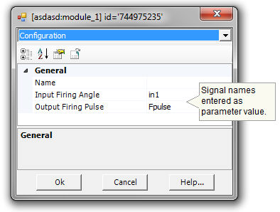
This time, instead of using a port connection, the user wants to port the Input Data Signal through a parameter on the module. The data wire leading into the module needs to be named –this is accomplished by using a Data Label. Then define a parameter in the module definition Parameters section.
|
|
|
Data Signal Named and Port Connection Removed from Module |
New Input Parameter in Parameters Section of Module Definition |
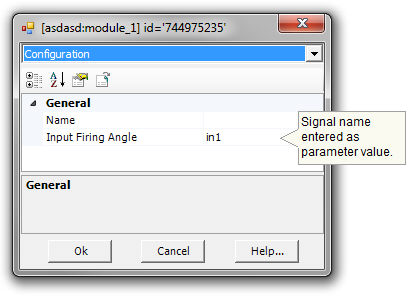
Module Component Parameter Dialog |
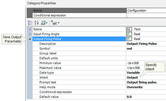
Say also that the user wants to bring the firing pulse output signal back out to the main page using a parameter. The first step (as before) is to define an Export component and connect it to the firing pulse output signal. The user names the export signal out. The final step is to define an output parameter in the module definition Parameters section.
|
|
Added Export tag in Canvas of Module |
New Output Parameter in Parameters Section of Module Definition |
The user may now input this new output signal to any other component on the main page.
|
|
Parent Canvas with Module and Controller with New Connection |
Module Component Parameter Dialog |
The aforementioned data signal porting can also be accomplished by means of Radio Link components.
![]()
Radio Links offer a 'wireless' method of porting the signals; that is there is no need for ‘hard-wired’ port connections, input parameters and Import/Export components. In fact, Radio Links make it possible to port signals simultaneously to multiple receiving points throughout the project from a single transmit point. This is analogous to a wireless broadcast, where multiple receivers can accept data from a single transmitter. See the Radio Links component help for more details.
EXAMPLE 5-3:
Consider again the project in Example 5-1. A user wants to modify the system so that the input signal in1 is transferred into the module by means of Radio Link components. The input data signal is first disconnected from the module and then reconnected to a Radio Link transmitter named in1.
Secondly, the input port connection is removed from the module definition Graphic section, as it is no longer required. Lastly, the Import component is removed and replaced with a Radio Link receiver. See Radio Links for more details on setting up the component parameters.
|
|
Parent Canvas View of Controller with Radio Link Transmitter |
Canvas of Module with New Radio Link Receiver |
NOTE: Radio Link components are not fully supported when using Multiple Instance Modules. Please contact the PSCAD Support Desk for more information.
If an electrical node needs to be represented within a module, then PSCAD must be informed of this requirement so that the network of electric nodes can be properly mapped. This is accomplished by using port connections and a special electrical node component called an XNode.
If you create a new module component by using the Component Wizard, the process of adding port connections and XNodes is fully automated. See Creating a New Component or Module later in this section for more details.
If you are editing an existing module, follow these general steps:
Edit the definition of the module. See Editing a Component or Module Definition in this section for more details.
Define an electrical port connection in the Graphic section (Graphic tab) of the module. See The Graphics Section for more details.
Add a corresponding XNode component on the module Schematic canvas. Each XNode must be named the same as its corresponding port connection.
EXAMPLE 5-4:
Consider a simple project that consists of a single-phase source bus connected to a module. The module Graphic section includes a single port connection named NA, which is connected to the source bus on the main Schematic canvas. The module canvas (i.e. Schematic view) consists simply of a Resistor component connected directly to a Ground component.
|
|
|
Main Canvas Containing a Module and Source |
Graphic View of Module Definition |
Schematic Canvas View of Module |
Here are a few important factors to remember when porting electrical signals into and out of modules:
XNodes cannot be placed on the project main page.
Only one instance of an XNode should exist within the module for a single port connection.
An XNode cannot be directly grounded. That is, do not connect a Ground component directly to an XNode. A ground may be connected directly to the corresponding electrical port connection however.