The PSCAD environment is a graphical user's interface to the EMTDC simulation engine. Therefore in order to control input variables or view simulation data, the user must provide EMTDC with instruction on which variables to make available for viewing or control. This process is performed graphically in PSCAD through a number of special components, sometimes referred to as runtime objects.
In order to record, display or control any data signals within the environment, the data signal must first be linked to a runtime object. Runtime objects are organized into three main groups:
Controls: Slider, Dial, Switch and Push Button
Recorders: Output Channel and RTP/COMTRADE Recorder
Display Devices: Control Panel, Graph, XY Plot, PolyMeter and PhasorMeter, Oscilloscope
Each runtime object performs a specific task, and may be used in combination with others to control and/or display data.
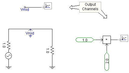
Channelling output refers to the directing of data signals for either online display in a graph or meter, or for output to file. This is accomplished by channelling the desired signal through an Output Channel component. For example, the image below shows how to channel a signal from a Voltmeter component (named Vmid), as well as how to channel an unnamed signal directly within the Schematic canvas:

NOTE: Output channel components cannot be directly connected to an electrical signal.
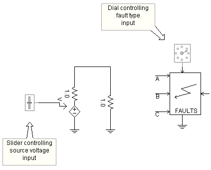
Controlling input data refers to using one of the control type runtime objects (i.e. Slider, Dial, Switch or Push Button) as a source to control a data signal. This is accomplished by simply adding a control object to the Schematic canvas. This signal can be input at any valid location in the schematic as shown below:

NOTE: The control objects cannot be manually adjusted (as they appear above) until they are linked to a control interface. See Online Controls and Meters for details.