The properties contained within this section are the most commonly accessed project parameters. Note that most of the settings found here can also be accessed via the Project tab of the ribbon control bar.
These settings are very important and are used quite often in every day simulation studies.
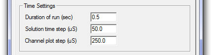
This is the total length of the simulation run, entered in seconds. If you start from time zero, this is the finish time of the run. If you start from a snapshot file (pre-initialized state), this is the length of run from the snapshot time.
This is the EMTDC simulation time step, entered in microseconds. The default is 50 ms, which is an optimum step for most practical circuits. However, users should make sure that the time step selected is suitable for their simulation. This input sets the value of the EMTDC internal variable DELT.
This is the time interval at which EMTDC sends data to PSCAD for plotting as well as writing data to output files. It is always an integer multiple of the EMTDC simulation time step. Usually a 250 ms plot step provides a reasonable resolution and speed.
Smaller sampling intervals (higher sampling rate) can decrease the simulation speed considerably due to an excessive transfer of data from EMTDC to PSCAD (without adding much to the plot resolution). Users can experiment with this number for a given project. If the sampling interval is too large, the waveforms may appear 'choppy'. If you are debugging the case, it is a good practice to plot every point in the simulation; that is, plot sampling time as equal to EMTDC simulation time step.
A trap that even the most experienced engineers can readily fall into is the setting of plot step too broad with respect to the level and period of noise in the signal. If a signal is periodic at a frequency similar to the plot step interval, the perceived output may be quite different to the actual signal. As a basic rule: If you are puzzled by the results observed from a plotted simulation output, run the case with the plot step equal to the EMTDC time step and compare the results.
NOTE: The plot step can be modified during a run (or after starting from a snapshot). You can change the value from the Project Settings dialog or via the ribbon control bar.
There are two ways to start a simulation in PSCAD: The standard method (i.e. from time = 0.0 seconds) or from a snapshot file.
The standard method to start an EMTDC simulation run is to simply start from an un-initialized state (i.e. from time t = 0.0). This is how simulations are started most of the time.
There may be instances when you would like to start your simulation from a pre-initialized state. Initial conditions are not available as direct entry into specific components, but it is possible to run a case to steady-state, and then take a snapshot at a specified instant during the run. All relevant network data will be saved to a snapshot file, from which you may start your case already pre-initialized.
An input field is included directly beside this field called Input File. Enter a name for the snapshot file to be used here. See Starting from a Snapshot for more details on how to create and start from a snapshot file.
NOTE: When you start from a snapshot file, make sure that you have not altered the circuit from which the snapshot was taken, otherwise an error may occur.
You can save all output channel signals in your project to a file for post processing. Output files are saved in standard ASCII format, and all data is stored in columnar format in steps of time according to the set plot step.
An input field is included directly beside this field called Output File. Enter a name for the file here. The output file will by default be located in the PSCAD Temporary Folder.
See Saving Output to File for more details.
There are two ways to utilize a snapshot file: Single and incremental snapshots.
An input field is included directly beside this field called Snapshot File. Enter a name for the snapshot file to be created here. Another input field is included called Time. Enter the time in seconds at which the snapshot is to be taken.
See Taking a Snapshot and Starting from a Snapshot for more details.
A single snapshot will be taken at the time specified in the Time field.
An incremental snapshot in the same file will take the first snapshot at the specified time and subsequent snapshots at equal intervals equal to this time. The snapshot file will be over-written every time, so you will end-up with a single file taken at the last time interval.
If you would like to save all snapshot files, select this option. You can save up to 10 distinct snapshots. If the number of files exceeds 10, the names will be reused starting from the beginning.
The file naming convention is:
base_name_##.snp
You are required to provide only the 'base_name' (in the Snapshot File field). The extension will be added automatically.
There are currently two methods for performing multiple runs in PSCAD – this one is the more basic of the two. This method is used in conjunction with the Current Run Number and Total Number of Multiple Runs components, which are available in the master library.
Another field is included directly beside the Multiple Run field called Output File. Enter a name for the multiple run output file here. Another input field is included called # runs. Enter the total number of runs here (this value is used to set the Total Number of Multiple Runs component).
NOTE: The other multiple run method involves the Multiple Run component, which is available in the master library. DO NOT enable this multiple run feature when using the Multiple Run component.
EXAMPLE 7-1:
Consider the simple comparator below. The Multiple Run parameter is enabled in the Project Settings dialog and set to 10 runs.
In this case, the comparator output is set to go low (0) when input A is less than or equal to 1.0 (i.e. the last two runs).
The remaining Runtime parameters are outlined below:
This parameter is used in correlation with starting the simulation from a snapshot file. Enabling this parameter will force the initial start time on all plots to display a 0.0 start time - regardless of what time the snapshot was taken. If disabled, the initial start time will be displayed as the time at which the snapshot file was created.
A user runs a case project to steady state, and then takes a snapshot at 0.5 seconds. The user then re-starts the simulation from the snapshot file created, and sets the Duration of Run parameter to 0.05 s.
If Remove Time Offset When Starting from a Snapshot is enabled, the simulation run will be displayed from 0.0 to 0.5 seconds. If disabled, from 0.5 to 0.55 seconds.
It is important to note here that this option changes displayed start time only. That is, if you are controlling breakers or faults for example, you must use the actual time. In Example 7-2 above, if the user wanted to open a breaker 0.01 seconds after starting from the snapshot, the breaker logic must indicate 0.51 seconds (not 0.01 seconds).
Selecting this option will turn off all output channels that are not being plotted in graphs, or monitored in meters. Enabling this option has the potential to greatly reduce the amount of storage for the simulation, as well as a slight simulation speed improvement.
NOTE: Unused output channel data will still be written to EMTDC output files if Save Channels to Disk? is enabled.
This option allows you to start a PSCAD run that can be connected with a manually started EMTDC case. See Deployment of an Integrated Debugger in Chapter 11 of this manual for more details.
This option will enable/disable Active Graphics in all components. Since the active graphics algorithm is processor intensive, disabling it will help speed up those cases that contain a lot of animation.