Ribbon
Schematic Canvas
Definitions Branch
New components (including modules and transmission segments) are created within the component wizard pane. The component wizard generates a new definition, and then creates a single instance of it (by default) for placement on the Schematic canvas. The user may then continue with the design, given this basic new component. For more on component design, see Component Design.
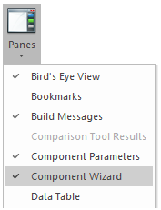
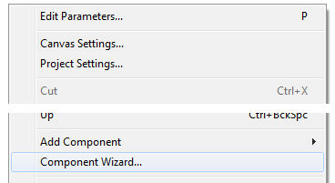
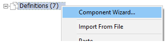
Open the component wizard pane by selecting either Component Wizard from the Panes drop list in the View tab of the ribbon control bar; or, move the mouse pointer over a blank area of any page, right-click and select Component Wizard; or, right-click on the definitions branch under the project node in the primary workspace window.
|
|
|
Ribbon |
Schematic Canvas |
Definitions Branch |
In any case, the Component Wizard pane will appear:

The component wizard environment consists of two main parts: The definition graphic and transmission segments canvases, as well as properties form. All of which are described in detail below.
Before getting into the details of the component wizard inner workings, here is how you can create a component quickly: In fact, there are a couple different ways:
|
Create Definition and Instantiate Button |
|
Select and Copy the Graphic, Then Paste on the Schematic Canvas |
The graphic canvas allows for some limited flexibility in the creation of the initial component graphic. Of course, the component graphics can be edited later, post-creation. See The Graphic Section for more details on that.
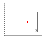
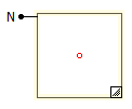
When the component wizard pane is invoked, you will notice a single default box graphic.

This graphic cannot be removed from within the component wizard; however it can be modified in terms of size and shape, by grabbing and stretching the box at the bottom-right corner.
The component wizard allows for ports to be added and moved around in a limited, yet malleable fashion. Ports may be added to the graphic in one of two ways:

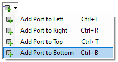
By default, the port will be added to the left-side of the box graphic.
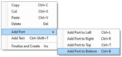
The Add Port button includes a drop list, which allows you to place the port directly on any side of the box:
Once a port has been added to the graphic canvas, you may move it around the box with a left-click drag action. However, the port will remain bound to the box graphic.
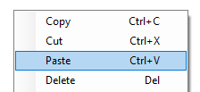
Ports may also be cut, copied, pasted and deleted, all via hotkeys or the right-click context menu:
Port properties may also be modified in the Properties Form (see below). To view port properties in the form, first select the port.
NOTE: The port will also have associated with it, a port label. This is a separate object, with separate properties.
For more information on port types (i.e. electrical, data, etc.) see Port Connections.
The component wizard allows for text labels to be added and moved around. Text labels may be added to the graphic in one of two ways:

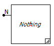
By default, the text label will be added to the centre of the box graphic, with the default name Nothing.
Once a text label has been added to the graphic canvas, you may move it around the canvas with a left-click drag action.
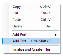
Text labels may also be cut, copied, pasted and deleted, all via hotkeys or the right-click context menu:
Text label properties may also be modified in the Properties Form (see below). To view port properties in the form, first select the port.
There are a few other functions available while working on the component wizard graphic canvas. These are described below:
Show Grid: This button toggles a grid display on the graphic canvas.

Show Origin: This button toggles the display of the origin point (red dot) on the graphic canvas.

Zoom Buttons: A zoom in and a zoom out is available for the graphic canvas.

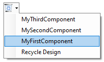
Recycle Button: If at any point during component creation you want to reset the component wizard environment, press the Recycle button. The recycler will track your previous work by maintaining a recycled list. To access any previous component, simply select it from the list. Note that this list is lost when the PSCAD application is closed.
Create Definition and Instantiate: Press this button when you are finished your component design. This action will create a new definition and attach a component instance to the mouse pointer.

The properties form is a dynamic display that lists the properties of whichever object is currently selected on the graphic or the transmission segments canvas.
|
|
|
|
Default Box Graphic |
Port |
Port Label |
Text Label |
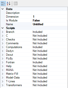
General
Property descriptions:
Name: Enter a name for the new component definition. This name must conform to Fortran standards (i.e. it cannot begin with a number or contain any spaces or other illegal characters). This name will be used in the coding of project source files, wherever this definition is used.
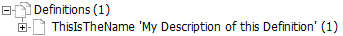
Description: Optional. Enter a description for the new component definition, which will be used for display in the workspace tree, definitions branch.
Is Module: Set this choice input to True if you want the new component to be a module (also referred to as a page component or a sub-page).
Dimension: This input sets the default dimension of any port added after the change. A dimension greater than one will also automatically thicken the default box graphic.
Script Segments
A list of all possible script segments to be included in the new definition are listed here. You may include or exclude them directly here, but this can also be managed using the script manager once the definition has been created. See Script Section in the Component Design chapter for details on definition scripts.
Each segment type in this list will possess it's own properties as well. To view these, simply click the arrow beside the script, to expand the list.
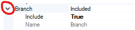
Each segment will include some common properties, as described below:
Include: Set this property to True if it is to be included in the initial creating of the definition.
Name: For display only.
However, some script segments (ex. Fortran, DSDYN and DSOUT) include addition properties, as described below:
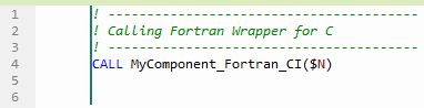
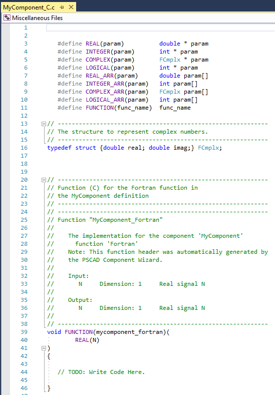
Auto Generate: Select either Default, C Interface, Fortran Interface or MATLAB Interface. This option enables the inclusion of a simple template (or boilerplate) interface to external code, in whichever language you choose. This includes the generation of an external file, which is placed in a folder called Resources, located in the same folder as your current project. For example, if the C Interface is enabled in the Fortran script segment:
|
|
C Interface Code in the Fortran Script Segment |
External, C File Contents |
If Default is selected, the component wizard will simply create the blank script segment.
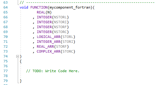
Storage Arrays: If Auto Generate | C Interface is selected, you have the additional option to include declarations of the EMTDC storage arrays in the external file generated. If this option is set to True, the declarations will appear as follows:
|
External, C File Contents (With Storage Declarations) |
General
Property descriptions:
Dimension: Enter a dimension for the port connection. Entering 0 indicates that this port is to assume the dimension of whatever it is connected to. Entering a 1 defines a scalar.
Electrical: Select Fixed, Removable, Switched or Ground. For more details on these options, see Electrical Node Types.
Is Internal: Electrical type ports only. Selecting True simply disables the compiler warning message indicating that an internal electrical, isolated node exists.
Type: Select the port type here: Electrical, Input or Output.
Display
Port property descriptions:
Name: Enter a Symbol name for the port. This name must conform to Fortran standards (i.e. it cannot begin with a number or contain any spaces or other illegal characters).
Draw Name: Select True to display the port label aside the port.
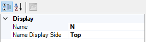
Port Label property descriptions:
Name: Enter a Symbol name for the port. This name must conform to Fortran standards (i.e. it cannot begin with a number or contain any spaces or other illegal characters).
Name Display Side: Select Left, Right, Top or Bottom. This refers to the placement of the port label, in relation to the port.
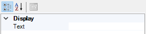
Display
Port property descriptions:
Text: Enter the text to be displayed in the text label graphic.
To create a new transmission line or cable, left-click the Transmission Segments tab. The graphic canvas will be overlaid as shown below:
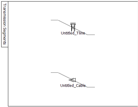
Left-click to select either the overhead transmission line, or the underground cable. Click the Create Definition and Instantiate button.
General
Transmission segment property descriptions:
Descriptions: Enter a description for the transmission line or cable definition. This is for display only, and will appear in the project definitions branch, as well as the workspace secondary window.
Name: Enter the segment name of the transmission line or cable definition.