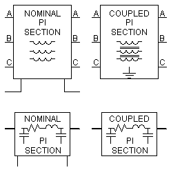

A p-section is primarily used to represent a very short overhead transmission line or underground cable. Although a p-section representation will provide the correct fundamental frequency impedance, it will not accurately model properties at other frequencies. In other words, p-sections provide a simplified means to represent transmission systems for steady-state studies (such as a load flow), but do not provide an accurate, full-frequency transient response.
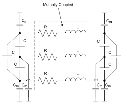
A p-section is formed by using lumped R, L and C elements, based on information entered by the user. The R and L elements are represented in matrix format and thereby provide coupling between the three phases. There is also both a mutual capacitance C and a capacitance to ground Cm at each end:

Coupled P-Section Representation in PSCAD
Whenever possible, the Coupled P-Section option should be chosen. This option uses the coupled RL transformer model in EMTDC (as shown above) to model the zero sequence effects, thus avoiding the extra neutral branch in the Nominal P-Section for the zero-sequence.
Important Notes on Nominal P-Section:
Caution should be exercised when using the Nominal P-Section option, in order to ensure that zero-sequence parameters and ground connections are correctly represented. The Nominal P-Section has neutral connections at each end of the line, with an RL zero-sequence branch connected between the neutrals. The zero-sequence component of current will therefore flow through this neutral branch (thus creating the higher zero sequence impedance), whereas the positive and negative-sequence components will add up to zero. All voltages should be measured as either line-to-line, or from the line to the neutral point (not to ground!). Similarly, faults should be applied from the line to the neutral (again, not to ground!).
The Nominal P-Section option should not be used when connecting to distributed transmission line models as they utilize a local ground concept.
More: |
Basic Overview Of Modeling Techniques Constructing Transmission Line Systems |
Zero Sequence Estimation Parameters
Surge Impedance, Travel Time Data