Configuring the Transmission Segment Component
Constructing the Sliding Fault
Setting Up Multiple Run Control
Tandem line configuration (or Tandem Lines) for both underground cable and overhead transmission segments was first introduced with PSCAD V5, in response to numerous requests for an easier way to automate a sliding-fault style study. The tandem lines feature combines multiple run control, parallel-processing and the transmission segment configuration components, to enable quick and efficient sliding-fault simulations.
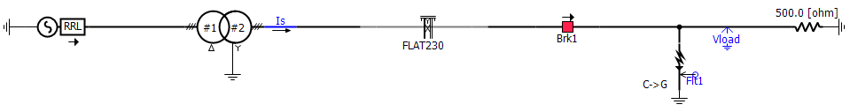
To set up a tandem line, you can start with any transmission line or cable configuration component, already defined in a case project. For the purpose of simplicity, let us use the simpleac.pscx example project in the Examples folder. The example project contains a single overhead transmission line, connecting a source to a load. The load side of the line is configured already with controllable fault and breaker components.
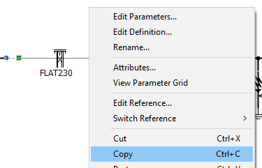
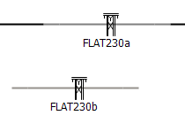
The transmission segment configuration component (Cable or TLine) needs to be duplicated, in order to facilitate the creation of both a Leading and a Trailing segment of the line. Since the line segments will be identical, except for their length, all that is required is that the component is copied and pasted to create a new instance. Immediately change the name of the two instances to distinguish them:
|
|
|
Copy the Component |
Paste the Component |
Rename the Components |
Both copies will share the same original definition, but their respective unique segment names will make them distinct. Here we chose to leave the name intact, but add a postfix to each to distinguish them. Leave the all other parameters in the Configuration category page, including Segment Length, untouched.
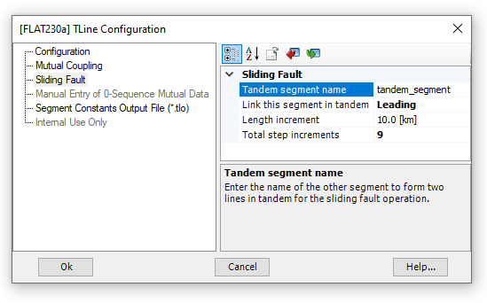
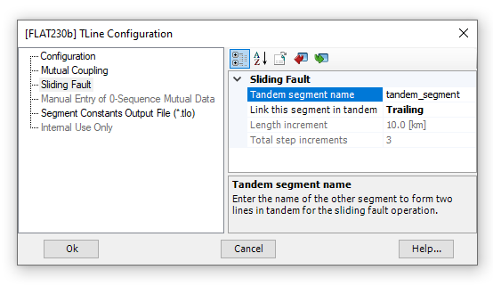
Next we need to define which will be the Leading and Trailing segments of the tandem line. Edit the parameters of each component to configure them for tandem line operation. For this example, FLAT230a is chosen as the Leading segment.
|
|
Configuring FLAT230a |
Configuring FLAT230b |
As displayed above, there are four parameters used to configure a tandem line:
Tandem Segment Name: This name must be identical in both the Leading and Trailing segment.
Link This Segment in Tandem: Choose Leading or Trailing. A tandem line is allowed one leading and one trailing segment.
Length Increment: Enter a length to increment the tandem line. Each multiple run, the Leading segment length will be increased by this increment. Simultaneously, the Trailing segment will be decreased by this same increment (creating the 'illusion' of a sliding fault).
Total Step Increments: The total number of times the tandem line segment lengths will be incremented/decremented.
NOTE: It is important to note, that the length increment, multiplied by the total steps, should remain less than the total length of the line (Segment Length). In this example, the total segment length is 100 km, so we are okay.
Now that our Leading and Trailing segments are configured, we can construct a sliding fault circuit. All that is required is that the fault circuitry appear in between the Leading and Trailing segments. In the simpleac.pscx example project we are looking at, this may look something like this:
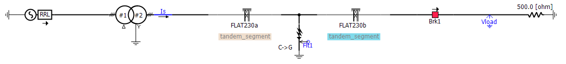
Note that the Leading and Trailing segments can be easily identified via a display tag that now appears on the component graphics.
The final step before you can run your sliding fault simulation, is to set up a multiple run to control the number of times run. To do this, simply edit the project settings, and set the Run Configuration setting to Standalone, and the #runs setting to the same number as the Total Step Increments defined above in the transmission segment configuration components. In this example, this is 9.
That's it! Run the simulation.
Note that if you need to collect the resulting data from each fault increment, ensure that project setting Save channels to disk? is enabled.