Examples of Units Entered in Component Input Fields
Component parameter units perform limited conversion and scaling, depending on the unit entered and the defined default (or Target) unit for that particular input parameter. The unit system includes base units for time, length, weight and speed (both translational and rotational), as well as electrical units, such as voltage, current and power.
To enable the unit system, click the associated check box in the Dynamics tab of the Project Settings dialog. This option is normally enabled by default.
Units are entered exclusively into component input parameter fields and may only be associated with literal input data: That is, units are invalid when using input variables or global substitutions. All entered units must be separated at least one space from the entered value. For example:
|
|
|
Examples of Units Entered in Component Input Fields |
The foundation of the unit system is the base unit. Base units represent all units that are recognized by the unit system. Use of units in an input field is optional, and if the input does not have a unit specification included with it, then the unit will assume that of the Target Unit for the input parameter. If units are specified, then the unit conversion is strict and will evaluate an input parameter field as indeterminate (#NaN) if it does not recognize the unit or fails to process a compound unit. All the base units, except a few noted exceptions, conform to the International System of Units (SI).
The following lists the valid (standard) base units recognized by the Unit System. All symbols are case sensitive and must appear exactly as shown to maintain validity:
|
|
Name |
Symbol |
Conversion Factor |
Description |
|
Electrical |
Volt |
V |
|
Electrical voltage |
|
Ampere |
A |
|
Electrical current |
|
|
Ohm |
ohm |
|
Electrical resistance |
|
|
Siemens |
S |
|
Electrical conductance 1 |
|
|
Siemens |
mho |
|
Electrical conductance 2 |
|
|
Siemens |
mhos |
|
Electrical conductance 3 |
|
|
Watt |
W |
|
Electrical power 1 |
|
|
Volt-Amps |
VA |
1 VA = 1.0 W |
Electrical power 2 |
|
|
Volt-Amps |
VAR |
1 VAR = 1.0 W |
Electrical power 3 |
|
|
Horsepower |
hp |
1 hp = 746.0 W |
Electrical power 4 |
|
|
Farad |
F |
|
Electrical capacitance |
|
|
Henry |
H |
|
Electrical inductance |
|
|
Tesla |
T |
|
Magnetic flux density |
|
|
|
|
|
|
|
|
Time |
Second |
s |
|
Time in seconds 1 |
|
Second |
sec |
|
Time in seconds 2 |
|
|
Second |
Sec |
|
Time in seconds 3 |
|
|
Minute |
min |
1 min = 60 s |
Time in minutes |
|
|
Hour |
hr |
1 hr = 3600 s |
Time in hours |
|
|
Day |
day |
1 day = 86400 s |
Time in days |
|
|
|
|
|
|
|
|
Frequency |
Cycles per Second |
Hz |
|
Cycles per second |
|
|
|
|
|
|
|
Length |
Metre |
m |
|
Length in metres |
|
Inch |
in |
1 in = 0.0254 m |
Length in inches |
|
|
Feet |
ft |
1 ft = 0.3048 m |
Length in feet |
|
|
Yard |
yd |
1 yd = 0.9144 m |
Length in yards |
|
|
Mile |
mi |
1 mi = 1609.344 m |
Length in miles |
|
|
|
|
|
|
|
|
Weight |
Gram |
g |
|
Weight in grams |
|
Pound |
lb |
1 lb = 453.59237 g |
Weight in pounds |
|
|
|
|
|
|
|
|
Rotational |
Revolutions |
rev |
|
Revolutions ( 1 [rev] = one complete revolution) |
|
Radian |
rad |
1 rad = 1/2p rev |
Angle in radians |
|
|
Degree |
deg |
1 deg = 1/360 rev |
Angle in degrees |
|
|
|
|
|
|
|
|
Other |
Revolutions per Minute |
rpm |
1 rpm = 1/60 rev/s |
Rotational speed in revolutions per minute |
|
Revolutions per Minute |
RPM |
1 RPM = 1/60 rev/s |
Rotational speed in revolutions per minute 2 |
|
|
Per-Unit |
pu |
|
Per-unit quantity |
|
|
Per-Unit |
p.u. |
|
Per-unit quantity 2 |
|
|
Percent |
% |
1 % = 0.01 pu |
Percent quantity |
The unit system utilizes a limited list of SI prefixes in order to allow for scaling of base units. Prefixes must precede a valid base unit, and may be inserted anywhere within compound units.
The following table lists all valid prefixes:
|
Name |
Symbol |
Scale Factor |
|
tera |
T |
1012 |
|
giga |
G |
109 |
|
mega |
M |
106 |
|
kilo |
k |
103 |
|
milli |
m |
10-3 |
|
micro |
u |
10-6 |
|
nano |
n |
10-9 |
|
pico |
p |
10-12 |
The unit system will determine the final conversion or scaling factor to apply, based on the target unit of the input parameter field. The target unit is the symbol entered in the Units field (i.e. the default unit) in the Parameters section of the component definition.
NOTE: You can view the target units of any component by invoking the View Properties dialog: Right-click on the component and select View Properties.
Target units are not limited to the base units alone, and may include prefixes by default (i.e. kA): In instances such as these, any prefixes in the target unit will be considered if further scaling is performed later on. In fact, this is quite common in the master library, where many target units are specified in [kA], [kV] or [uF].
EXAMPLE 5-5:
The master library component 3-Phase 2-Winding Transformer contains an input parameter called Winding 1 Line to Line Voltage (RMS), whose target unit is specified as kV in the Units field.
|
|
|
|
3-Phase 2-Winding Transformer |
Input Field Property Settings (V1) |
A user enters data into the Winding 1 Line to Line Voltage (RMS) field as 0.153 [MV]. Given that the target unit contains the prefix k, the application will understand that any quantity entered in this parameter field must be converted back to kilovolts (not the base unit of volts [V]). Therefore in this case, the quantity will be multiplied by a scale factor of 1000 to convert it from 0.153 [MV] back to 153.0 [kV].
Whether or not target units include prefixes is normally of no concern, unless of course a new component is being designed. Provided that the base of the entered unit matches that of the target, all scaling and conversion is performed automatically.
The most useful aspect of the unit system is the ability to convert one unit to another, be it an imperial/metric conversion or simply converting from one form to another, such as radians to degrees.
Converting units from one form to another is relatively straightforward, the only rule is that the conversion must take place within the same base unit class; for example, [m] to [ft] (both units measure length) or [sec] to [hr] (both units measure time). Valid prefixes may be included in the conversion as well, for instance, [km] to [mi].
EXAMPLE 5-6:
A user is designing a transmission line tower. The default units for the tower dimensions are in metres, but the user's specification sheets give the dimensions in feet. The unit system will allow the user to enter this data directly in feet, without the need to convert to metres.
|
|
|
|
Transmission Line Tower Component |
Transmission Line Tower Parameter Dialog |
PSCAD will automatically convert all units entered in feet, back to metres before the Line Constants Program is called to solve the line.
The unit system will recognize three types of arithmetic operator within the unit brackets, in order to allow for combining (or compounding) units together. These are:
|
Arithmetic Operator |
Description |
|
* |
Multiply |
|
/ |
Divide |
|
^ |
Exponent |
When dealing with compound units, it important to note some simple rules. Failure to follow these rules may result in invalid unit conversion:
The sequence in which the arithmetic operators occur in the entered unit must match that of the target unit.
|
|
Entered |
Target |
|
Correct: |
[hp*min/MVA] |
[MW*s/MVA] |
|
Incorrect: |
[hp/MVA*min] |
The total number of arithmetic operators in the entered unit must match that of the target unit. That is, you cannot substitute an exponent for multiple 'divisions' or 'multiplications'.
|
|
Entered |
Target |
|
Correct: |
[ft*ft] |
[m*m] |
|
Incorrect: |
[ft^2] |
Multiple 'divide' symbols are not allowed - only one 'divide' per compound unit may exist.
|
|
Entered |
Target |
|
Correct: |
[lb*ft/s] |
[kg*m/s] |
|
Incorrect: |
[lb/s/ft] |
EXAMPLE 5-7:
The master library component Wind Turbine contains an input parameter called Machine rated angular speed, whose target unit is specified as rad/s in the Units field.
|
|
|
|
Wind Turbine |
Input Field Properties Dialog (Wrat) |
A user enters data into this parameter as 60.0 [Hz]. This is a valid unit in this case as both Hz and rad/s are essentially the same type of measure, where 2p [rad/s] = 1 [rev/s] = 1 Hz (see Base Units above).
The master library component Wind Turbine (described above) also contains an input parameter called Air Density, whose target unit is specified as kg/m^3 in the Units field.
|
|
|
Input Field Properties Dialog (Airden) |
A user enters data into this parameter as the equivalent in imperial units 0.07647 [lb/ft^3]. The units converter will apply the appropriate scale factors to this number so that the quantity will appear to EMTDC as it is still in kg/m^3.
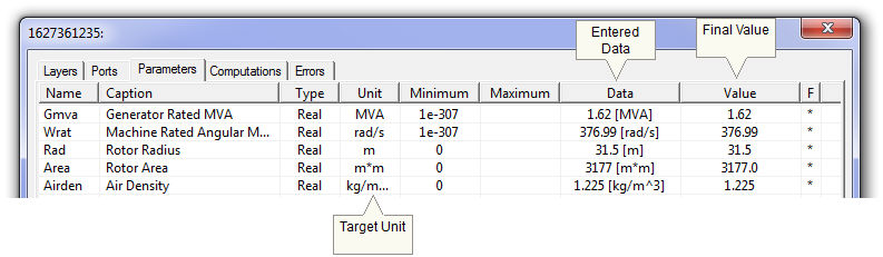
It is generally recommended to ensure that any unit conversions performed in a component are verified before proceeding with the simulation. This can be accomplished easily by using the Properties Viewer. This dialog displays the target unit, the entered data, and the final value following the conversion.
The following diagram shows these three parameters following the changes made the 'Air Density' input, as outlined in Example 5-4.
|
|
|
Wind Turbine Air Density Parameter |