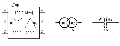
This component models a 3-phase, 2-winding transformer and is based on the classical modeling approach.
Options are provided so that the user may choose between either a magnetizing branch (linear core), or a current injection routine to model magnetizing characteristics. If desired, the magnetizing branch can be eliminated altogether, leaving the transformer in 'ideal' mode, where all that remains is a series leakage reactance. A magnetic hysteresis model is also available in this component.
This component is the equivalent of three, 1-Phase, 2-Winding Transformers connected in a 3-phase bank, where the user can select the winding interconnections to be Y or D on either side. Inter-phase coupling is not represented in the classical transformer models. An equivalent circuit is shown below, using 1-phase transformers:
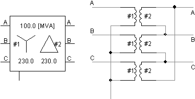
If inter-phase coupling is essential for your study, then you should choose the equivalent UMEC transformer model.
More: |
Transformer Name |
|
Text |
|
Just an identifier. A name should be entered here to avoid compilation warnings |
|
|
|
|
|
3-Phase Transformer MVA |
|
REAL |
Constant |
The 3-phase apparent power rating of the transformer [MVA] |
|
|
|
|
|
Base Operation Frequency |
|
REAL |
Constant |
The base frequency of the electrical system, in which the transformer resides [Hz] |
|
|
|
|
|
Winding # Type |
|
Choice |
|
Select the connection type for the specified winding # - Star (Y) or Delta (D) connected |
|
|
|
|
|
Delta Lags or Leads Y |
|
Choice |
|
Select whether the D-connected winding voltage will lead or lag the Y-connected winding voltage by 30° |
|
|
|
|
|
Positive Sequence Leakage Reactance |
|
REAL |
Constant |
The total positive sequence leakage reactance of the transformer. This can be calculated based on short-circuit test results [pu] |
|
|
|
|
|
Ideal Transformer Model |
|
Choice |
|
Select Yes or No. This input must be Yes when modeling core saturation
NOTE: 'Ideal' transformer should not be confused with an ideal ratio changer. 'Ideal' here simply means that the magnetizing branch has been eliminated (leakage reactance is still present as well) |
|
|
|
|
|
Eddy Current Losses |
REAL |
Constant |
The eddy current portion of the no-load core losses, based on transformer rating. Hysteresis losses may also be added here if hysteresis is not modeled. Winding losses are not to be included in this value [pu]. |
|
|
|
|
|
|
Copper Losses |
|
REAL |
Constant |
Enter the total copper losses for the transformer. Equivalent winding resistances are calculated based on this entry so that losses are distributed evenly among all the windings. These resistances are then placed in series with the windings [pu] |
|
|
|
|
|
Tap Changer on Winding |
|
Choice |
|
Select the winding number on which to place the on-line tap changer (or none).
See On-Line Tap Changer for more details |
|
|
|
|
|
Graphics Display |
|
Choice |
|
Select 3-phase view or single-line view |
|
|
|
|
|
Display Details |
|
Choice |
|
Select Yes or No. This input is only functional in Single Line View and will display MVA and winding voltages near the component |
Winding # Line to Line Voltage (RMS) |
|
REAL |
Constant |
The RMS voltage rating of the corresponding winding # [kV] |
NOTE: See Adjusting Saturation Properties and Transformer Magnetic Hysteresis for more details on these inputs
Saturation Enabled |
|
Choice |
|
Select Yes or No to enable or disable the core saturation routine.
NOTE: Always set the transformer to 'ideal' when enabling saturation. Otherwise, both the magnetizing branch and the saturation routine will both be used. |
|
|
|
|
|
Place Saturation on Winding |
|
Choice |
|
Select Middle, Winding #1 or #2.
Middle is the preferred option, whereas specifying the actual winding number is left in for legacy support. Selecting the winding number will place the saturation current injection directly on that winding. Note that this can cause ideal loop problems when performing certain types of studies (such as black start).
See Adjusting Saturation Properties for more details. |
|
|
|
|
|
Hysteresis |
|
Choice |
|
Select None, Basic Model, or Jiles-Atherton.
The Basic Model models hysteresis based a translation on the transformer l-I characteristic, whereas the Jiles-Atherton model involves a conversion from an M-H loop to a B-H loop characteristic.
See Transformer Magnetic Hysteresis for more details. |
|
|
|
|
|
Inrush Decay Time Constant |
|
REAL |
Constant |
The decay time for the transformer inrush current [s].
This option is enabled only when Hysteresis | None is selected. |
|
|
|
|
|
Time to Release Flux Clipping |
|
REAL |
Constant |
Time interval from start-up in which the model will 'clip' (limit) the calculated flux linkage values. This is simply a modeling 'trick' to prevent instability at start-up [s].
This option is enabled only when Hysteresis | None is selected. |
|
|
|
|
|
Air Core Reactance |
|
REAL |
Constant |
Usually approximately twice the leakage reactance [pu]. |
|
|
|
|
|
Magnetizing Current |
|
REAL |
Constant |
The percentage of primary winding current that flows through the transformer magnetizing susceptance. This value can be calculated based on the open-circuit test results. The magnetizing susceptance is calculated based on this value [%]. |
|
|
|
|
|
Knee Voltage |
|
REAL |
Constant |
The knee point voltage corresponding to the knee point of the saturation curve [pu]. |
|
|
|
|
|
Remanent Flux Core # |
REAL |
Constant |
Enter
the remanent flux for each core as a per-unit value of the
peak flux at rated voltage [pu].
This option is enabled only when Hysteresis | Basic Model or Hysteresis | Jiles-Atherton is selected. |
|
|
|
|
|
|
Loop Width |
REAL |
Constant |
Enter
the loop width as a percentage of the Magnetizing
Current
[%].
This option is enabled only when Hysteresis | Basic Model is selected. |
|
|
|
|
|
|
Nominal Flux Density (T) |
REAL |
Constant |
Enter
the nominal flux density corresponding to the saturation curve
[T].
This option is enabled only when Hysteresis | Jiles-Atherton is selected. |
|
|
|
|
|
|
Magnetic Material |
Choice |
|
Select
Custom,
or Default.
This option is enabled only when Hysteresis | Basic Model is selected. |
Magnetic Characteristics of the Material
NOTE: This category is enabled only if Hysteresis | Jiles-Atherton and Magnetic Material | Custom is selected.
Domain Flexing Parameter |
|
REAL |
Constant |
This parameter represents the contribution of reversible magnetization process. |
|
|
|
|
|
Domain Pinning Parameter |
|
REAL |
Constant |
This parameter has a direct impact on the width of the loop [A/m]. |
|
|
|
|
|
Parameter to Adjust K with M |
|
REAL |
Constant |
This parameter adjusts the domain pinning parameter with magnetization for better representation of the shoulder area. |
|
|
|
|
|
Inter-Domain Coupling |
|
REAL |
Constant |
|
|
|
|
|
|
Saturated Anhysteretic Magnetization |
|
REAL |
Constant |
[A/m]. |
|
|
|
|
|
Coefficient # of Anysteretic Curve |
|
REAL |
Constant |
|
NOTE: If no name is specified, these output signals will not be monitored.
Name for Phase to Phase Winding Current [kA] |
REAL |
Output |
Name for the specified phase to phase current [kA] |
|
|
|
|
|
|
Name for Phase Current (+in)[kA] |
REAL |
Output |
Name for the specified phase line current. This is both the line and the phase current if winding is Y-connected, and line current only if winding is delta connected. This parameter is positive into the winding from the line [kA] |
Monitoring of Magnetic Core: #
Name for Flux Density Phase # [T] |
REAL |
Output |
Name for the flux density [T]. |
|
|
|
|
|
|
Name for Phase # Flux Linkage [kWb-N] |
REAL |
Output |
Name for the calculated flux linkage [kWb-N]. |
|
|
|
|
|
|
Name for Magnetic Field Intensity Phase # |
REAL |
Output |
Name for the magnetic field intensity. This output is enabled only when Hysteresis | Jiles-Atherton and Saturation Enabled | Yes is selected. |
|
|
|
|
|
|
Name for Phase # Magnetizing Current [kA] |
|
REAL |
Output |
Name for the magnetizing current [kA]. |