![]()
The Feedback Loop Selector is used to identify a break point within a feedback loop.
The output signals of all EMTDC system dynamics (controls) components are initialized to zero before the simulation starts, and sorted in an order of calculation, specified by an internal sequencing algorithm. The feedback loop selector can help to organize feedback loops in such a way that the calculation of the output signals are correct.
Notes:
Figures A to E illustrate a simple control circuit that it is used to explain how system dynamics components are sorted, and how the feedback loop selector affects the sequence. The components are sorted in order starting from sources to sinks. In this example, there are two sources, both being Commonly Used Constants components. There is only a single sink, which is the Output Channel (PGB) component.
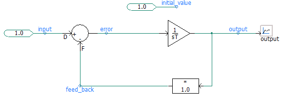
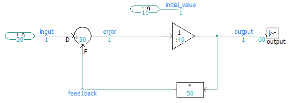
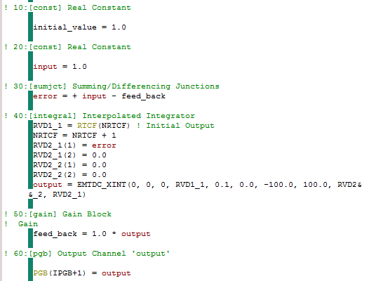
Figure A - Simple Control System
|
|
Figure B - Automatically Assigned Sequence Numbers (Schematic and Corresponding Generated Code)
Figure B shows the sequence numbers assigned automatically by the sequencing algorithm. These numbers represent the order in which these components will appear in the system dynamics code. For example, the output of the integrator component is calculated following the output of the summing junction, and so on. The signal called initial_value will be the first to appear in the generated code because it has the smallest sequence number on this schematic canvas. This signal is used as an input parameter to the integrator component, to provide it with an initial output value. Thus, the input of the gain component will eventually be set to 1.0, as its sequence number (50) directly follows the calculation for the integrator (40).
The second signal to be calculated, following initial_value, is input as it is next in the sequence (20). Hence, input is also equal to 1.0 at time zero. The next in line is the error signal, whose value will be the input signal minus feed_back signal (the feed_back signal remains unprocessed (equal to 0.0) at this point, as its value is defined after the summing junction by the gain component (50): Thus, the error is equal to 1.0 - 0.0 = 1.0 when processed. The process continues until all output signals from each component are calculated. Table A shows a summary of the sequenced calculations.
Component |
Sequence Number |
Output (at Time Zero) |
Output Signal |
| Real Constant | 10 |
1.0 |
initial_value |
| Real Constant | 20 |
1.0 |
input |
| Summing/Difference Junction | 30 |
1.0 |
error |
| Integrator | 40 |
1.0 |
output |
| Gain | 50 |
1.0 |
feed_back |
| Output Channel | 60 |
1.0 |
output |
Table A - Execution Order and Signal Output for Figure B
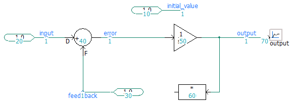
Figure C - No Feedback Loop
Figure C illustrates how the algorithm sorts the components when there is no feedback loop in the system. The error signal is now 0.0 because the input signals to the summing junction (20 and 30) have been processed before the summing junction (40), in contrast to that shown in Figure B. Figures D and E show the effect of adding the feedback loop selector component, when used before and after the gain block.
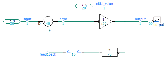
Figure D - Feedback Loop Selector Following Gain Component
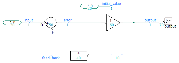
Figure E - Feedback Loop Selector Preceding Gain Component
Note that the results as given by the control circuits in both Figure D and E, will be identical to that given in Figure A. In Figure D, the output of the feedback loop detector (10) is 0.0. This is due to the fact that the output from the gain component (50) remains unprocessed at the time. In Figure E, the output of the feedback loop detector (10), and hence the output of the gain (40), are both uninitialized due to the unprocessed integrator (60).
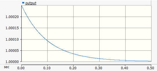
Figure F - Output of Control Circuit in Figure A, D and E (Feedback Loop Not Initialized)
Although the output signal should have a value of 1.0 continuously throughout the simulation, it does not due to the fact that the error signal is non-zero at time zero. This results initially in a non-unity output on the integrator.
The Feedback Loop Selector component provides parameter configuration to provide an initial output value at time zero, in order to ensure proper initialization when used in circuits, such as Figures A to E above. See the Initial Values category description below to find the appropriate parameter entry.
For example, if the feedback loop selector in Figure D above is initialized to a value of 1.0 at time zero, then the error signal will be calculated as 0.0 (error = input - feed_back). The output signal will now remain a 1.0 throughout the simulation.
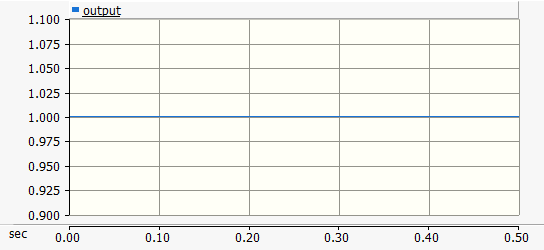
Figure F - Output of Control Circuit in Figure A, D and E (Feedback Loop Initialized)
More: |
Knowledge Base Example |