Transmission systems considered to be electrically short (i.e. the propagation delays are negligible) can be represented with reasonable accuracy by a simple circuit consisting of a series-impedance and shunt-admittance. If the total shunt-admittance is halved and placed at each end of the circuit with the series-impedance between the two ends, the resulting equivalent circuit is referred to as a p-section [16].

Figure 8-30 – Single-Phase P-Section Equivalent Circuit
Where,
|
|
(8-86) |
and,
|
|
The sending end voltage and current respectively |
|
|
The receiving end voltage and current respectively |
|
|
Total series impedance |
|
|
Total shunt admittance (normally purely capacitive) |
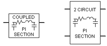
The Line Constants Program is not used by EMTDC for the calculation of p-section parameters. This is due to the fact that p-sections are entirely passive, and can be represented directly as part of the EMTDC conductance matrix. The PSCAD Master Library includes a 'coupled' p-section model, which equivalences a single, three-phase, mutually coupled circuit. There is also a double circuit 'coupled' p-section component, where both circuits are three-phase and mutually coupled.

Figure 8-31 – Coupled P-Section Components in PSCAD
For more information on these components, please see the respective topics in the PSCAD On-Line Help.
Long-line correction is required when attempting to accurately equivalence a long transmission line as a coupled p-section circuit. A 'long' transmission line can be defined as any line exceeding approximately 200 to 250 km in length [16], although this is surely open to interpretation.
Regardless of the actual defined length, p-section equivalent circuits will become less and less accurate as the line becomes longer. This is mainly due to the fact that a p-section does not account for the uniform distribution of line parameters. It is possible however, to derive a set of long-line corrected, lumped parameters so that the p-section equivalent circuit does indeed provide a better representation.
The Line Constants Program displays the long-line corrected data directly in the Output File (*.out). This information is provided specifically for users who wish to develop their own, multi-circuit p-section equivalents, using the Line Constants program as a starting point. The long-line correction is performed directly on the elements of the modal impedance ZM and modal admittance YM matrices as follows:
|
|
(8-87) |
|
|
(8-88) |
Where,
|
|
Modal propagation constant |
|
|
Eigenvalues of the YZ matrix |
|
|
Line length [m] |
The long-line corrected modal parameters are then transformed back to the phase domain before being displayed in the output file.