The UMEC (Unified Magnetic Equivalent Circuit) transformer model is based primarily on core geometry. Unlike the classical transformer model, magnetic coupling between windings of different phases, in addition to coupling between windings of the same phase, are taken into account.
In PSCAD, the following transformer core structures can be represented using the UMEC model:
Single-phase units with up to four windings.
Three-phase, three-limb units
Three-phase, five-limb units
For more details on the background theory of the UMEC transformer model, see [5].
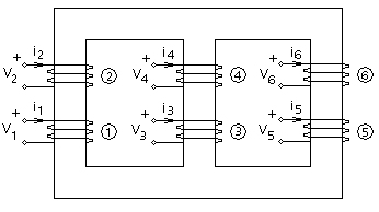
Consider the three-phase, three-limb transformer shown below:
Figure 6-12 - Schematic Representation of the Three-Phase, Three Limb Transformer (2 Windings per Phase)
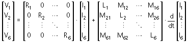
The voltage-current relationship for the six coils is given by:
|
(6-33) |
Where,
|
Winding resistance |
|
Winding self-inductance |
|
Mutual inductance between windings i and j |
The elements Li and Mij in Equation 6-33 are dependent on the core dimensions, the magnetic properties of the core material and the number of turns in different windings.
Exact core dimensions, along with information about the number of turns and magnetic characteristics, are not generally available to the user. The UMEC model overcomes this drawback by deriving the elements of the inductance matrix, based on the commonly available test data - these include the open and the short circuit tests.
The transformer core, along with windings 1 and 3 are shown below:
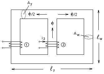
Figure 6-13 - Transformer Core Flux Due To Winding 3 Current
If a current i3 is passed through winding 3 with all other windings kept open-circuited, the following equations describe the current-flux relationship:
|
(6-34) |
Where,
|
Reluctance of the winding limb |
|
Reluctance of the yoke |
|
Physical length of limb (w) and yoke (y) |
|
Cross-sectional area of winding limb (w) and yoke (y) |
|
Permeance of limb (w) and yoke (y) |
Therefore for this case,
|
(6-35) |
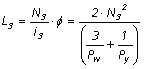
The self-inductance of winding 3 is defined as:
|
(6-36) |
The mutual inductance between windings 1 and 3 is defined as:
|
(6-37) |
Similar expressions can be derived for the other inductance terms in Equation 6-33.
The following example illustrates the approach adopted by the UMEC models to evaluate the above inductance terms when all the necessary information is not available.
Consider the two simple inductors shown below:
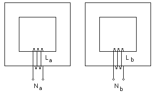
Figure 6-14 - Simple Inductors with Cores
The inductances La and Lb take the form:
|
(6-38) |
Where,
|
Permeance of the magnetic path |
The response of coils 'a' and 'b' to an electrical signal will depend on the values of La and Lb. Even if Pa and Pb are not equal, we can still select the number of turns in each coil so that La = Lb. The UMEC approach takes advantage of this fact and assigns the value Vi to the number of turns Ni, so that:
|
(6-39) |
Where,
|
The rated voltage of the winding in kV |
Although the exact dimensions are not known, it is reasonable to assume that the user is provided with a scaled drawing of the transformer. The following aspect ratios can be defined based on such a drawing:
|
(6-40) |
|
(6-41) |
Thus substituting these values into Equation 6-36 for the magnetic configuration in Figure 6-13 (and assuming that μw = μy, we get:
|
(6-42) |
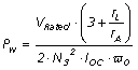
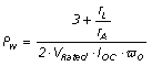
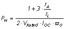
If winding 3 is then subjected to an open-circuit test (with all other windings kept open-circuited),
|
(6-43) |
Where,
|
Rated voltage |
|
Open-circuit test current in winding 3 |
|
Rated frequency |
By combining Equations 6-42 and 6-43, the permeance of a winding limb can be found as:
|
(6-44) |
Assign the rated voltage value to the number of turns,
|
(6-45) |
Similarly, the permeance of the yoke can be given as
|
(6-46) |
The following illustrates the derivation of 5-limb core aspect ratios:
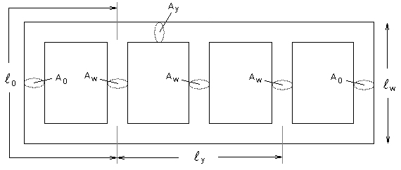
Figure 6-15 - A 5-Limb Transformer Core
Yoke/Winding Limb Ratios:
|
(6-47) |
|
(6-48) |
Yoke/Outer Limb Ratios:
|
(6-49) |
|
(6-50) |
The UMEC transformer models treat core saturation differently than the classical models: Here, the piecewise linear technique is used to control the model equivalent branch conductance.
The non-linearity of the core is entered directly into the model as a piece-wise linear V-I curve, which makes full use of the interpolation algorithm for the calculation of exact instants in changing of state range. See Switching and Non-Linear Elements for more details.
Once Pw and Py are calculated in this manner, all the off-diagonal elements in the transformer inductance matrix can be assigned the appropriate value.
The leakage flux is treated in a similar manner. The corresponding inductances are estimated based on short-circuit test results and are added to the self-inductance terms, which forms the diagonal elements.
Thus, in the UMEC models, the transformer inductance matrix is derived based on the nameplate data (V1, V2, etc.), the core aspect ratios (rA and rL), and short-circuit and the open-circuit test results.
Detailed information of the UMEC approach can be found in [5] and [6]. Interested users are encouraged to refer these publications.