CCIN as a Compensating Current Source
Compensating Current Source Injections
The node-based GGIN interface is used primarily for node to ground operation. It may be used as a node-to-node branch interface, but this is not recommended. The GEQ branch interface described above should be used instead, in order to ensure that present and future EMTDC features are supported. The GGIN interface will slowly be phased-out over time.
The GGIN interface is composed of two parts: A Norton current source and an equivalent branch conductance. These two quantities are represented by the following EMTDC intrinsic variables:
Variable Name |
Type |
Description |
CCIN(NN,SS) |
REAL |
Sets the value of current injected into the network. The current source is inserted between node NN and ground. |
GGIN(NN,SS) |
REAL |
Sets the conductance value of the Norton current source |
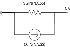
Table 5-9 – Intrinsic Variables to Define the Node-Based Electric Interface Branch
Figure 5-6 - GGIN Electric Interface Branch
The CCIN current source in Figure 5-6 represents the total value of current injected into node NA from ground. It is very important to note that from the perspective of EMTDC, only one CCIN current source or GGIN conductance can exist on a single node. Therefore, the user must ensure that if using a CCIN current source, the value of that particular source be summed with the overall CCIN for that node. This will ensure that if this CCIN source is connected to a node containing other CCIN sources, its value will combine with the existing source values. The same procedure must be performed when providing a GGIN conductance as well. Listing 5-20 below contains a code snippet, which illustrates this concept.
! ! Calculate the value of this CCIN source and GGIN conductance: ! THIS_CCIN = CURR THIS_GGIN = 1.0 / R ! ! Combine this current and conductance with existing CCIN and GGIN ! (may or may not exist). ! CCIN(NA,SS) = CCIN(NA,SS) + THIS_CCIN GGIN(NA,SS) = GGIN(NA,SS) + THIS_GGIN ! |
Listing 5-20 – Code Snippet Illustrating Support for Multiple CCIN and GGIN at a Single Node
NOTE: The values of CCIN and GGIN are reset to zero by the main program at the beginning of each time step, and therefore must be defined each time step.
In order to use the CCIN current source, it must first be enabled at time zero. This is accomplished through the following intrinsic variable:
Variable Name |
Type |
Description |
ENABCCIN(NN,SS) |
LOGICAL |
Indicates whether or not an CCIN source at node NN is enabled. Set as .TRUE. to enable control of CCIN. |
Table 5-10 – Intrinsic Variable to Enable a CCIN Source
The CCIN current source can be used without the equivalent conductance GGIN: As a simple ideal current source injection into a specified node. This is particularly useful when modeling a non-linearity with as a compensating current source, as discussed in the section Switching and Non-Linear Elements in the chapter Electric Network Solution.
EXAMPLE 5-6:
The following example code shows how to use CCIN and GGIN to represent a simple inductor.
! SUBROUTINE U_BGN_SIMPLE_L(SS,NA) ! ! Common block and module include files: ! INCLUDE ′nd.h′ INCLUDE ′s0.h′ INCLUDE ′s1.h′ INCLUDE ′rtconfig.h′ ! ! Argument List: ! INTEGER NA ! EMTDC node number INTEGER SS ! EMTDC subsystem number ! ! Local Variables: ! INTEGER MY_NRTCF ! ! Set local pointer values and increment: ! MY_NRTCF = NRTCF NRTCF = NRTCF + 1 ! ! Initial Branch Definition (t = 0.0): ! ENABCCIN(NA,SS) = .TRUE. RTCF(MY_NRTCF) = DELT / (2.0*0.001) ! RETURN END ! |
Listing 5-21 – Construction of a CCIN Current Injection within BEGIN Subroutine
! SUBROUTINE U_DYN_SIMPLE_L(SS,NA) ! ! Common block and module include files: ! INCLUDE ′nd.h′ INCLUDE ′s0.h′ INCLUDE ′s1.h′ INCLUDE ′emtstor.h′ INCLUDE ′rtconfig.h′ ! ! Argument List: ! INTEGER NA ! EMTDC node number INTEGER SS ! EMTDC subsystem number ! ! Local Variables: ! REAL CURR INTEGER MY_NSTORF, MY_NRTCF ! ! Set local pointer values and increment: ! MY_NSTORF = NSTORF MY_NRTCF = NRTCF NSTORF = NSTORF + 1 NRTCF = NRTCF + 1 ! ! Calculate new history current: ! CURR = RTCF(MY_NRTCF)*(-VDC(NA,SS)) + STORF(MY_NSTORF) ! STORF(MY_NSTORF) = CURR + RTCF(MY_NRTCF)*(-VDC(NA,SS)) ! ! Define CCIN and GGIN: ! CCIN(NA,SS) = CCIN(NA,SS) + STORF(MY_NSTORF) GGIN(NA,SS) = GGIN(NA,SS) + RTCF(MY_NRTCF) ! RETURN END ! |
Listing 5-22 – Construction of a CCIN Current Injection within DSDYN/DSOUT Subroutine
An interface to the EMTDC electric network solution (no matter how complicated the model is) will always boil down to a representation by a simple equivalent Norton current source in parallel with a conductance. Each time step the current source magnitude im(t) is calculated, based on the branch voltage and the current from the previous time step. The result is injected back into the system, affecting nodal voltages. In the next time step, these modified voltages affect the calculation of current injections, and so on.
There are instances however, where a current source may be utilized without a corresponding conductance – to model a non-linearity for example. Care must be exercised when representing electric models in this manner: Due to the finite calculation step, the current source injection im(t) will be dependent on the node voltage from the previous time step, thus any sudden change in node voltage would appear as an open circuit to the current source, resulting in spurious voltage spikes and numerical problems at the interface node [5]. To rectify this, a large Norton resistance (small conductance) should be placed between the interface nodes in order to ensure that finite impedance is always present.
The addition of the conductance G will introduce a small error into the interface, which should be corrected. This is accomplished through the insertion of a compensating current source as shown in Figure 5-7.
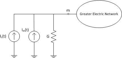
Figure 5-7 – General Interface to the EMTDC Electric Network with Compensating Current Source
Where,
|
(5-3) |
Instead of injecting just the calculated current im(t), a total compensated current im(t) + iC(t) is injected, where v(t - t) is the interface voltage at the previous time-step.
This method has proven effective in maintaining the stability of electric models over the years. For instance, this concept allowed for the simulation of multiple rotating machine interfaces on the same bus.