Instead of writing our own code to define the voltage source, we can use EMTDC internal subroutines to do it for us. We simply need to ensure that all of the subroutine arguments are defined in the component before we call it. The subroutines we will use are as follows:
E_BRANCH_CFG: This routine is used to initialize the branch properties that we have already outlined in the previous section.
E_1PVSRC_CFG: This is the runtime configuration routine for one of the EMTDC single-phase voltage sources. It is used in the Single-Phase Voltage Source Model 2 component in the master library.
EMTDC_1PVSRC: This is the actual EMTDC single-phase voltage source routine. It is used in the Single-Phase Voltage Source Model 2 component in the master library.
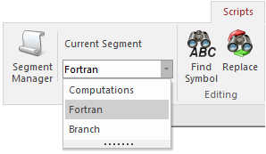
Edit the component definition and in the Script section, navigate to the Fortran segment.
Add the following script to the segment (you may copy directly from here):
#BEGIN CALL E_BRANCH_CFG($BRN,$SS,1,0,0,$R,0.0,0.0) CALL E_1PVSRC_CFG(1,0,1,$Vrms,$f,0.0,$R,0.0,0.0,0.0,0.0,$tr) #ENDBEGIN #STORAGE LOGICAL:1 INTEGER:6 REAL:8 RTCF:4 #LOCAL REAL RVD1_1 #LOCAL REAL RVD1_2 #LOCAL REAL RVD1_3 #LOCAL REAL RVD1_4 ! Single Phase AC source: Type: R RVD1_1 = RTCF(NRTCF) RVD1_2 = RTCF(NRTCF+1) RVD1_3 = RTCF(NRTCF+2) RVD1_4 = RTCF(NRTCF+3) NRTCF = NRTCF + 4 CALL EMTDC_1PVSRC($SS,$BRN,RVD1_4,.TRUE.,RVD1_1,RVD1_2,RVD1_3) |
The block of script between the #BEGIN and the #ENDBEGIN directives is runtime configurable code that will be inserted into the BEGIN section of the system dynamics in EMTDC. Here, we are calling two EMTDC subroutines, which combined will initialize both the branch parameters and the source control. Descriptions of the argument lists are given as follows:
E_BRANCH_CFG(NBR,M,ER,EL,EC,RO,HL,FC)
Argument List:
NBR : Number of the branch being configured.
M: Subsystem number where the branch resides.
ER: Include/exclude resistance (1 or 0).
EL: Include/exclude inductance (1 or 0).
EC: Include/exclude inductance (1 or 0).
R0: Resistance value [W]
HL: Inductance value [H]
FC: Capacitance value [mF]
E_1PVSRC_CFG(AC,SPEC,TYP,VM,F,PH,R,L,RP_C,P,Q,TC)
Argument List:
AC : AC or DC source (1 or 0 respectively).
SPEC: Internal values or at source terminal (0 or 1 respectively).
TYP: Impedance type (R = 1).
VM: RMS voltage [kV].
F: Frequency [Hz].
PH: Phase angle [deg]
R: Resistance value [W]
L: Inductance value [H]
RP_C: Capacitance value [mF]
P: Active Power output
Q: Reactive power output
TC: Ramp-up time [s].
The storage allocation (#STORAGE) is necessary as it provides memory usage information for dynamic memory dimensioning in EMTDC. The LOGICAL, INTEGER and REAL allocations are the storage usage for the EMTDC_1PVSRC subroutine. The RTCF allocation is used to dimension the runtime configurable storage.
Directly preceding the call to the EMTDC_1PVSRC subroutine is the extraction of initialized values from the RTCF storage array. The values stored in this array are defined in the BEGIN section at the beginning of the simulation (within the E_1PVSRC_CFG subroutine) and remain constant. Extracting this data from storage ensures that the initialized values are instance-dependent – that is they are specific to wherever this component code is placed in the system dynamics.
The last bit is the actual call to the subroutine that controls the source throughout the simulation: EMTDC_1PVSRC.
EMTDC_1PVSRC(M,NBR,RT,AC,VP, W, A)
Argument List:
M : Subsystem number where the branch resides.
NBR: Number of the branch being configured.
RT: Ramp-up time [s].
AC: True if an AC source.
VP: Peak voltage [kV].
W: Frequency [rad/s].
A: Phase angle [rad].