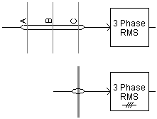

The Three Phase RMS Voltmeter measures the three-phase RMS voltage at three specific electrical nodes in a circuit. The component may be set to output one of two different algorithms, depending on the users preference:
Analog: This function calculates the combined RMS value of three separate time domain input signals (representing the 3 phases of a bus voltage). The output is passed through a first order lag function internally (with a time constant given by the input parameter Smoothing Time Constant), before being externally output. For more details on this algorithm, see the [VM3PH2] Voltage Meter (3-Phase,L-L,RMS) in the EMTDC Tools Library.
Digital: This calculation method using a 'moving data window approach', where the RMS value for a buffered set of data is calculated each time step. The size of the buffer is determined by the input parameter # of Samples in a Cycle. For more details on this algorithm, see the [DGTL_RMS3] Digital RMS Meter (3-Phase,L-L,RMS) in the EMTDC Tools Library.
The choice of which function is best suited for a particular study depends on its use. The Digital method will provide a very smooth output signal, which works well for control. The Analog method will produce ripple in the output signal, depending on the input signal frequency and the RMS Smoothing Time Constant parameter, but can respond much faster to changes.
The Node Loop component must be used to provide the required input to this component as shown below:

More: |
Name for Identification |
Text |
Optional text parameter for identification of the component. |
||
Meter Type |
|
Choice |
|
Select Analog or Digital. |
|
|
|
|
|
Connected to a Node Loop With |
|
Choice |
|
Select 3 Phase View or Single Line View. |
|
|
|
|
|
Rated Voltage for Per-Unitizing (L-L,RMS) |
|
REAL |
Constant |
Enter the rated system voltage for per-unitizing the output signal [kV] |
|
|
|
|
|
Smoothing Time Constant |
|
REAL |
Variable |
Enter the time constant for the internal Real Pole smoothing function [s]
This function is enabled only when Meter Type | Analog is selected. |
|
|
|
|
|
Fundamental Frequency |
|
REAL |
Constant |
Enter the signal fundamental frequency [Hz]
This function is enabled only when Meter Type | Digital is selected. |
|
|
|
|
|
# of Samples in a Cycle |
|
INTEGER |
Literal |
Enter the number of samples to be taken for one cycle of fundamental frequency. The number of samples cannot be greater than the number of time steps within one cycle of Fundamental Frequency.
This function is enabled only when Meter Type | Digital is selected. |
|
|
|
|
|
Initial Voltage (L-L, RMS) |
|
REAL |
Constant |
Enter the initial RMS voltage value for the output signal. This value is optional and will be loaded into the internal sampling buffer at time t = 0.0 s.
This function is enabled only when Meter Type | Digital is selected. |