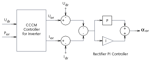
The CCCM Controller for Rectifier and CCCM Controller for Inverter components model a voltage dependent voltage order characteristic for the HVDC Combined Coordinated Control Method (CCCM). CCCM combines and coordinates the DC current and DC voltage control at each DC station. For more details on this model, see [6].

Special algebraic functions are incorporated into the CCCM controller components to coordinate inputs to generate both a DC voltage order (Uor at the rectifier and Uoi at the inverter) and a DC current order (Ior at the rectifier and Ioi at the inverter). To understand the symbols used in the above figures more clearly: 'U' represents DC voltage, 'I' represents DC current, 'P' represents DC power. The subscript 'o' represents an ordered value and subscript 'd' represents a measured value. All signals are in per unit on the DC rated base voltage, current and power. The location of the signal with a subscript 'r' is at the rectifier and 'i' at the inverter. Gamma (g) is the extinction angle and b = p - a where a is the firing or ignition angle.
The DC voltage and current orders, generated by the special algebraic functions, are compared with their measured quantities, the errors summed for input to PI controllers, which independently generate the firing angle order at each DC station. Note that the PI controller with each CCCM controller component and the summing of its input in the diagrams above, are not included with the component and must be added separately by the user.
The key to the operation of the CCCM controller is that the rectifier essentially operates as a power controller and the inverter as a resistance controller. A voltage dependent current order limit (VDCOL) is also imbedded in the special algebraic functions of the CCCM Controller Component resulting in operating characteristics similar to that shown below:
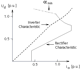
The characteristics of the CCCM control method are helpful in case of weak networks, which require not only fast power recoveries for their stabilization, but also the highest efficiency through extinction angle control.
The gains and time constants of the proportional-integral controllers must be optimized for large signal disturbances. This can be done by trial and error or by using the Multirun feature to search for the best settings.
NOTE: The Manitoba HVDC Research Centre Inc. makes no claim to the accuracy and validity of this CCCM controls model. It is distributed as a point of interest and education and is developed solely from [6].
Related Topics