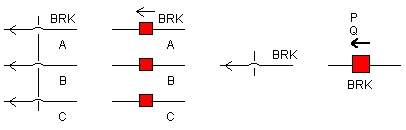
This component simulates of three-phase circuit breaker operation. The ON (closed) and OFF (open) resistance of the breaker must be specified along with its initial state.
This component is controlled through a named input signal (default is BRK), where the breaker logic is:
0 = ON (closed)
1 = OFF (open)
Three-Phase Breaker operation is virtually identical to that described for the Single-Phase Breaker. The breaker control can be configured automatically by using the Timed Breaker Logic component, or the Sequencer components. The breaker may also be controlled manually through the use of on-line controls, or through a more elaborate control scheme.
More: |
Single Pole Operation |
|
Choice |
|
Select Yes or No. If Yes is selected, all three breaker phases will be operated independently of each other. Therefore, three input control signals will be required. |
|
|
|
|
|
Open Possible at any Current? |
|
Choice |
|
Select Yes or No. If No is selected, the breaker will wait for the absolute value of the current to be less than the specified Current Chopping Limit. |
|
|
|
|
|
Use Pre-Insertion Resistance? |
|
Choice |
|
Select Yes or No. See Pre-Insertion Resistance for more details. |
|
|
|
|
|
Current Chopping Limit |
|
REAL |
Constant |
Enter the limit for current chopping [kA]. See Open Possible at any Current? above. |
|
|
|
|
|
Graphics Display |
|
Choice |
|
Select 3-Phase View or Single Line View |
|
|
|
|
|
Graphics Display 2 |
|
Choice |
|
Select Low Voltage Display or High Voltage Display |
|
|
|
|
|
Display Power Flow |
|
Choice |
|
Select Yes or No. If Yes is selected, the 3-phase real and reactive power flowing through the breaker will be monitored and displayed |
Breaker Main DataBreaker Main Data
Breaker Name |
|
INTEGER |
Variable |
Enter a name to identify the breaker. This name will also act as the breaker input control signal |
|
|
|
|
|
Breaker Phase Name |
|
INTEGER |
Variable |
Enter a name for the input control signal for the specified phase. This input is only used when Single Pole Operation | Yes is selected |
|
|
|
|
|
Breaker OPEN Resistance |
|
REAL |
Constant |
Enter a large value to represent the OFF (open) state of the breaker. This should be in the order of 1.0 x 10⁶ (default) [W] |
|
|
|
|
|
Breaker CLOSED Resistance |
|
REAL |
Constant |
Enter a small value to represent the ON (closed) state of the breaker. This should be in the order of 1.0 x 10⁻³ (default). See Ideal Branch for more details [W] |
Pre-Insertion DataPre-Insertion Data
NOTE: These parameters are enabled only if Use Pre-Insertion Resistance? | Yes is selected. See Pre-Insertion Resistance for more details.
Pre-Insertion Resistance |
|
REAL |
Constant |
The value of Pre-insertion resistance. This should be smaller than the OFF (open) resistance and larger than the ON (closed) resistance [W] |
|
|
|
|
|
Time Delay for Closing Breaker (X) |
|
REAL |
Variable |
Enter the time delay between the ON (closed) signal and actual closing of the specified breaker phase. After this time delay, the specified breaker phase will close on to the pre-insertion resistance [s] |
|
|
|
|
|
Time Delay for Bypassing Pre-Ins. (X) |
|
REAL |
Constant |
Enter the time delay between the ON (closed) signal and the bypassing of the pre-insertion resistance. If this time delay is smaller than the Time Delay for Closing Breaker, the pre-insertion resistance will not be inserted before closing the specified breaker phase [s] |
|
|
|
|
|
Post-Insertion Removal |
|
Choice |
|
Select at next current zero or after specified time. This control specifies whether to remove the post insertion resistance at the next zero-crossing of current or following a specified time. |
|
|
|
|
|
Minimum Time for Post-Ins Removal |
|
REAL |
Variable |
Specifies the time after which the post insertion resistance is removed [s]. This field is enabled only if Post-Insertion Removal | Yes is selected. |
Internal OutputsInternal Outputs
Name for Breaker Current (kA) |
|
REAL |
Output |
Name for the specified breaker phase current [kA] |
|
|
|
|
|
Name for Calculated Zero Seq. Current (kA) |
|
REAL |
Output |
Name for the calculated zero-sequence current [kA] |
|
|
|
|
|
Name for Breaker Status |
|
INTEGER |
Output |
Name for the open or closed status signal for the specified breaker phase |
|
|
|
|
|
Name for Active Power |
|
REAL |
Output |
Name for the active power flowing through the breaker [MW] |
|
|
|
|
|
Name for Reactive Power |
|
REAL |
Output |
Name for the reactive power flowing through the breaker [MVAr] |
|
|
|
|
|
Name for Voltage Across Breakers |
|
REAL |
Output |
Name for the measured voltage signal across the breaker [kV].
NOTE: As this is a three-phase breaker, this output signal will be a 3-element array. |
Animation StatesAnimation States
Breaker Phase Status |
|
Choice |
|
Select Open or Closed to set the initial animation state (red or green) of the specified breaker phase |
|
|
|
|
|
Active Power |
|
REAL |
Variable |
Enter the active power value for display at time t = 0.0 |
|
|
|
|
|
Reactive Power |
|
REAL |
Variable |
Enter the reactive power value for display at time t = 0.0 |