The properties contained within the Mapping section are related to EMTDC network solution conductance matrix optimization.
The input parameters involved here are outlined below.
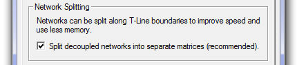
Matrix solution methods can be intensive, requiring a large amount of computing power, especially if frequently switching branches are involved. If this option is enabled, larger networks will be reduced into smaller sub-networks, or subsystems.
Once the main electric network has been split into subsystems, each subsystem can be solved independently. Say for example a large FACTS device (with many frequently switched branches) is located within its own subsystem, but part of a much larger network. By splitting the main network into subsystems, only the local subsystem, harbouring the FACTS device, need be resolved when a switching event occurs. The speed benefits here can be tremendous.
See Subsystems in Electric Networks in the EMTDC manual for more details.
The input parameters involved here are outlined below.
Optimize Node Ordering is a PSCAD based algorithm, which re-numbers nodes in the EMTDC electric network conductance matrix, so as to optimize solution speed. The electric network conductance matrix is optimized using a Tinney algorithm to exploit matrix sparsity. For more information on matrix optimization, please see [7], [8], [9] and [10].
Frequently switching branches are identified and re-ordered, so as to optimize conductance matrix re-triangularization following a change in branch conductance (a switch). The switch-ordering algorithm splits nodes into two types:
Nodes not attached to switching elements or nodes that have switching elements connected, but do not switch frequently (i.e. breakers and faults).
Nodes that have switching elements connected that switch frequently (i.e. thyristor, GTO, IGBT, diode, arrester, Variable RLC, etc.).
NOTE: Electrical connections in user-defined components are set as node type 2 by changing the electrical connection port type to Switched.
The switch-ordering algorithm moves the frequently switched nodes (i.e. type 2) to the bottom of the conductance matrix. The benefits to EMTDC solution speed are proportional to the number of nodes and the number of switching branches in a given electric network. For more information on matrix optimization, please see references [7], [8], [9] and [10].