![]()
According to that discussed previously, it follows then that a network of lumped R, L and C elements, will be represented in EMTDC as an equivalent circuit of resistive branches and current sources. The resistors are time invariant, except when they are modeled as non-linear or if a specific switching occurs. The equivalent current sources on the other hand, are time and history dependent and must be updated every time step.
Such a structure lends itself to processing by simple matrix methods. Using nodal analysis, a conductance matrix |G| is formed from the inverse resistance value of each branch in the equivalent circuit. |G| is a square matrix, whose size is determined by the number of nodes in the network under study. A column matrix |I| is formed where each element consists of the sum of all current sources at a node.
EXAMPLE 3-1:
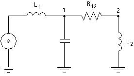
Consider a simple R, L, C two node network with its equivalent circuit as shown below:
|
|
|
|
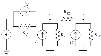
Figure 3-3 - RLC Equivalent Network in EMTDC
The inductors and capacitors are replaced in each case, by an equivalent resistor and current source. The nodal equations are formed as follows:
At node 1:
|
|
(3-4) |
At node 2:
|
|
(3-5) |
These equations are reduced to their matrix form as follows:
|
|
(3-6) |
Or in short form:
|
|
(3-7) |
The solution to the node voltages defined by column matrix V is then:
|
|
(3-4) |