Best advantage of EMTDC can be made if the electric network to be modeled can be split into discrete subsystems. This is particularly possible when distributed transmission lines or cables separate the electric network.
When EMTDC was first developed, the importance of minimizing the size of the conductance matrix, in order to efficiently represent HVDC systems, was realized. The simulation of these systems involved (and still do) many switching operations. Each time a power electronic device is switched in EMTDC, its resistance value changes and the conductance matrix must be re-triangularized or re-inverted. In larger systems, with matrix dimensions in the thousands, this can substantially decrease simulation speed and efficiency.
EXAMPLE 3-4:
Consider a 10,000 node electric network containing 50 network clusters, with 200 nodes evenly distributed in each cluster. The number of stored elements without splitting into subsystems (i.e. one large non-sparse matrix) would be:
Stored Elements = 10,000 x 10,000 = 100,000,000
The number of stored elements after splitting into subsystems (i.e. 50 non-sparse matrices of 200 x 200 nodes each) would be:
Stored Elements = 200 x 200 x 50 = 2,000,000 (50 times less memory required)
The time for performing an LU matrix decomposition is approximately the same as without any subsystem splitting. However, subsystems create performance advantages when you consider the time required to perform interpolation and switching operations. When an interpolation-switch-interpolation sequence is performed, it will affect only one subsystem, rather than the entire system of equations.
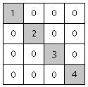
When distributed transmission line or cable models are used to transmit between smaller clusters of electric networks, it is possible to effectively split these clusters and solve them independently. Since distributed line models represent travelling waves, then a switching operation (or source perturbation) at one end of the line, will not impact the electric circuit at the opposite end within the same time step, but at some definable number of time steps following the disturbance. The network clusters at each end can then be considered as de-coupled, discrete subsystems, as no off-diagonal matrix elements will appear between them. Mathematically, this means that a separate conductance matrix can be created for each discrete subsystem and processed independently from other subsystems and their respective conductance matrices. Figure 3-7 represents four conductance matrices representing four de-coupled subsystems.
Figure 3-7 - De-Coupled Subsystems
In PSCAD, an electric network can only be split into subsystems by using distributed transmission lines or cables.
Splitting the conductance matrix into subsystems will result, in most cases, in a sparse matrix. That is, a matrix containing zero-elements that are not involved in the system solution (as shown above).
EMTDC does not store in the sparse format but compromises: It stores conductance matrix data in a sequential, non-sparse basis. In other words, some zero elements of the matrix are stored, but are not considered as active subsystems. The addresses of non-zero elements in each subsystem are stored in integer vectors, and are used to access the non-zero elements only. Keeping the storage sequential may not be the most memory efficient method possible, but it has performance advantages: Disk/RAM/cache transfers can be streamed more effectively by the Fortran compiler, compared to pure 'random' allocated storage of a sparse matrix vector quantity.