Electric Networks: Limitations to Protection
With a simple click of the mouse, this feature will convert a page module hierarchy into an equivalent, non-module component, complete with associated source files and optional compiled binary files. Referred to as blackboxing, it allows a mixture of both control and electrical systems to be designed and maintained graphically, only to be quickly collapsed and compiled at will; thereby protecting intellectual property for when models are distributed to clients.
In essence, PSCAD is (and always has been) a source code generator for the EMTDC simulation program. Both modules and standard (non-module) components are combined to form the source defining a structured, sequential program, which includes a unique set of subroutines to represent each module in the project. All components may possess a combination of parameters and ports. When module components are coded in Fortran, these ports and parameters are used to define the arguments for the corresponding subroutine. Non-module components combine to represent the body of the subroutine, corresponding to the page module in which they reside.
Beginning in and around 2011, requests for instructions on how to convert module components to equivalent, independent external source, began to increase. This trend involves using PSCAD module hierarchies to generate Fortran source (ex. a device controller). The generated Fortran is then manually manipulated to remove the internally dependent code required by PSCAD and EMTDC, thereby creating external source that may be called from within a standard component. This effectively conceals the graphical design of the circuit, hiding the contents within the external source. The source is normally compiled into an object (*.obj) file or static library (*.lib) before it is supplied to the client, providing protection for the provider’s intellectual property. The custom component may also be further customized to include a Branch segment to represent the electric network, plus ports and other required attributes – the end result being a fully ‘blackboxed’ version of the source module component.
Blackbox was first introduced into PSCAD with the release of v4.5, but supported only pure control systems, forcing users to separate controls into individual page modules prior to blackboxing.. This continued into v4.6 as well. The version of blackbox included in v5.0 and onwards however, supports both electrical and control system models mixed together within the same module, and even electrical networks that span across a module hierarchy (with a few restrictions of course).
NOTE: Unlike pure control systems, electric network topology information cannot be fully hidden, due to the manner in which PSCAD communicates electric network information to EMTDC. This information is written to the map (*.map) and data (*.dta) files (both ASCII text files), which is read by the EMTDC executable when the simulation is launched. For more information on this, see Electric Networks: Limitations to Protection below.
Blackbox performs all the necessary steps required to convert a page module hierarchy in PSCAD into a user-defined component, including associated source code. The following functions are executed automatically:
Fortran Source Generation: PSCAD already generates Fortran source, however this code is written specifically to interact with EMTDC as part of the simulation project, and is not formatted to be used as independent, external source. Blackbox will generate Fortran source code specifically formatted to be used with EMTDC, as an external file.
Automatic Object/Library file Creation: An option to compile the generated source file into an object file is provided. Note that if the module being blackboxed contains other modules within it, all object (*.obj) files created will be bound together into a static library (*.lib) file. See Application Options: Blackboxing for more details.
Automatic Component Creation: A component definition and instance is created, based on the contents of the module hierarchy. This includes ports, parameters, graphics and relevant script segments.
With any automated process, there are restrictions that must be adhered to before using the feature. These are explained below.
Runtime objects and radio links are not supported by the blackbox feature, and so therefore the module schematic cannot contain any of these components.
If the module you want to blackbox contains some or all of these components, then they must be removed and/or substituted by supported components. Input-based components, such as the slider, switch and dial, can be substituted in one of two ways: If it is important to be able to control the variable after blackboxing, the preferred method is to move them out of the module so that their signal can be passed in via a port or parameter:
|
|
Inside Module Schematic |
Outside Module Schematic |
However, if a particular signal attached to say, a slider for example has been tuned to a certain value, and this value will no longer change, then it is sufficient to just replace the slider with a constant tag, set to the slider's current setting. The same is true for switches and dials.
The module component you are blackboxing cannot contain any transmission lines or cables at all. There is a couple of reasons for this: First, any electric network that is included as part of a blackbox will be forced to a single subsystem. This reason, plus the fact that there is currently no way to represent a transmission line or cable within a non-module component. If your electric network contains transmission lines or cables, then these must either be converted to equivalent pi-section components, or you must arrange each individual network between the transmission lines into modules, and blackbox them separately.
It is important to note that when a blackbox component is created from a module that contains an electric network. The higher level details of that network (i.e. it's topology) will not be fully hidden. This is due to the manner in which PSCAD communicates the electric network information to EMTDC. This information is written to the project map (*.map) and data (*.dta) files (both ASCII text files), which is read in by the EMTDC executable (generated when the project is compiled) when the simulation is launched.
For example, let us have a look at the ac_switch.pscx example case from the PSCAD examples folder. If we were to take the simple power electronic circuit included in that example, place it inside a module and blackbox it, this is what a client would be able to glean from the resulting map and data files, once the blackboxed component is placed in a project, and the project is compiled:
|
Original Schematic of Page Module to be Blackboxed |
|
|
Circuit Information in the Data File Following Compile of the Project in which the Blackboxed Component Resides (Passive Branches Disabled) |
Graphical Representation of the Data File Information (Passive Branches Disabled) |
As can be seen above, the end-user would be able to reconstruct the circuit topology directly from the data file produced, once the project that the blackboxed component resides in is compiled. However, the parameter settings for the source are unknown. The user will not be able to determine what type of switch exists: It is simply written in as a default breaker, with no other information. The only issue that does remain is that passive element values, such R, L and C, can be gleaned from the data file. To alleviate this problem, a user-controlled option called Passive Branches, which is be default enabled, is available.
A user-controlled option called Passive Branches, is available to enable the hiding of passive element values. This option is enabled by default. What it does is simply replaces R, L and/or C elements with a call to the Runtime Configurable Passive Branch component. This effectively moves the actual element values directly into the Fortran source, thereby hiding them when the source is compiled into a static library or object file. The associated Branch segment statement for that branch, which gets written to the Data file, contains dummy values.
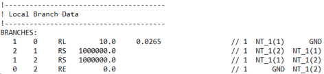
So if we were to look at the above example again: With the Passive Branches option enabled, the data file would look as follows:
|
|
Circuit Information in the Data File Following Compile of the Project (Passive Branches Enabled) |
Graphical Representation of the Data File Information (Passive Branches Enabled) |
There are a few application level options that may be adjusted to help customize how and where your blackbox component, and associated files, are created. These can all be found within the Application Options dialog.
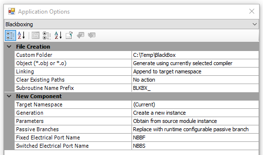
For more details on these user-controlled control options, see Application Options: Blackboxing.
Before creating a blackboxed component, it is important that you familiarize yourself with this entire topic, including the user-controlled options described above. Once you are confident in your knowledge, you can create a blackbox simply by right-clicking on the page module and selecting Generate | Blackbox.
See the topic Blackbox a Module for more details.