Vsource Properties
Isource Properties
It is possible to monitor quantities internal to the component, for display on plots and meters. This may be accomplished by defining an internal output variable. In this tutorial, we will set-up such variables to monitor source voltage and branch current.
There are two methods to do this. The older method is to use the #OUTPUT directive. The newer way (first introduced in v4.5) is to use a value field of intent output directly, without the need for an #OUTPUT directive. Both methods are presented below.
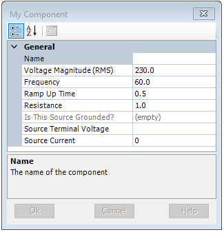
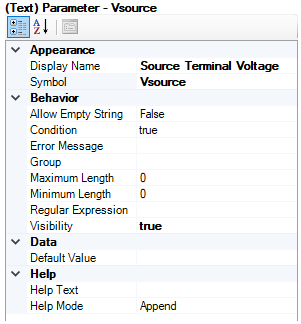
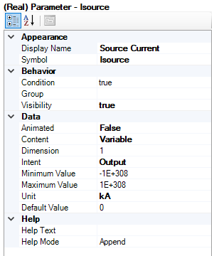
Edit the component definition and in the Parameters section, add a text field and a value field: The value field with Symbol name Isource and Description Source Current (ensure that Intent is set to Output); the text field with Symbol name Vsource and Description Source Terminal Voltage.
|
|
|
Vsource Properties |
Isource Properties |
Edit the component definition and navigate to the Fortran segment. Extract the current in this source branch (i.e. from branch BRN), using the CBR internal variable as follows:
$Isource = CBR($BRN, $SS) |
The value given by CBR($BRN,$SS) will be used to define the value of the output parameter Isource. Note that $SS substitutes the number of the EMTDC subsystem that this branch is part of.
Extract the node voltage from port connection NA to G or NB with an #OUTPUT directive statement and using the VDC internal variable. Remember that we have added expression statements that allow users to directly connect the source branch to ground. So, the branch voltage measurement will depend on which port connections are enabled. We can then choose a branch statement according to the Is this source grounded? choice field.
Your Fortran segment should then look similar to the following when completed:
#BEGIN CALL E_BRANCH_CFG($BRN,$SS,1,0,0,$R,0.0,0.0) CALL E_1PVSRC_CFG(1,0,1,$Vrms,$f,0.0,$R,0.0,0.0,0.0,0.0,$tr) #ENDBEGIN #STORAGE LOGICAL:1 INTEGER:6 REAL:8 RTCF:4 #LOCAL REAL RVD1_1 #LOCAL REAL RVD1_2 #LOCAL REAL RVD1_3 #LOCAL REAL RVD1_4 ! Single Phase AC source: Type: R RVD1_1 = RTCF(NRTCF) RVD1_2 = RTCF(NRTCF+1) RVD1_3 = RTCF(NRTCF+2) RVD1_4 = RTCF(NRTCF+3) NRTCF = NRTCF + 4 CALL EMTDC_1PVSRC($SS,$BRN,RVD1_4,.TRUE.,RVD1_1,RVD1_2,RVD1_3) ! $Isource = CBR($BRN, $SS) ! #IF gnd == 1 #OUTPUT REAL Vsource {$VDC:NA:G} #ELSE #OUTPUT REAL Vsource {$VDC:NA:NB} #ENDIF |
Any text field with a Symbol name identical to those defined above (i.e. Isource and Vsource), will act as internal output variable ports for the component. Any variable name entered into either the Source Current or Source Terminal Voltage text fields will create signals which, when connected to an Output Channel, can be plotted.