All objects and fields associated with either the Graphic or the Parameters sections will possess an input field labelled Conditional Statement. Within these fields, the user may add statements to either enable or disable the object, or make the object visible or invisible according to the logic specified in the statement.
The primary purpose of conditional statements is to either enable or disable an object (such as an input field), or to make an object visible or invisible (such as a graphic object).
The user may construct conditional statements by using both Arithmetic and Logical Operators, where the condition values themselves are always based on the value of a choice list. Through conditional statements, the operation and appearance of the component becomes instance-based and is controllable by the user.
A component designer wants to change the appearance of a component according to user-selected input. The component graphic is to be either an ellipse or a rectangle, depending on a choice list with Symbol name Type. The choice list specifies two choices: Ellipse, which is given the integer value 0, and Rectangle, which is given the integer value 1.
In the component Parameters section, the designer adds a single choice list:
In the component Graphic section, the designer draws a simple ellipse and a simple rectangle:
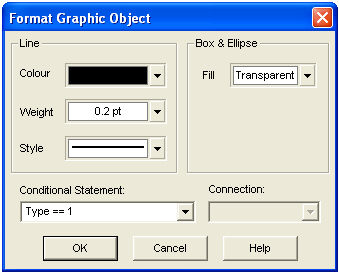
In the properties dialog for the Graphic Objects, the following text is added to the respective Conditional Statement input fields:
|
|
Ellipse Property Settings |
Rectangle Property Settings |
If a user selects Ellipse in the choice list, only the ellipse object will appear in the component graphic. If Rectangle is chosen, only the rectangle will appear.
Conditional statements are not limited to a single logical truth. It is possible to use several logical conditions in one statement. For example, say there was another choice list added to the component of Example 9-2 with Symbol name Type2. Now assume that in order for the ellipse object to be visible on the component graphic, it is required that Type2 have a value of 3 (in addition to Type having a value of 0). Then the following conditional statement would need to appear in Conditional Statement field of the ellipse object:
(Type == 0) && (Type2 == 3)
The above states: If Type equals 0 and Type2 equals 3, then make the ellipse visible.
Arithmetic Operators may also be included in conditional statements. For example, the following statement is also valid:
(Type + Type2 == 3)
The above states: If the sum of Type and Type2 equals 3, then make the ellipse visible.
NOTE: Care must be exercised when using the divide (/) function, as a divide by zero error can occur.
As component graphics become larger and more complicated, the graphical working environment can become quite unruly – especially when many conditional statements are used.
Fortunately, there is a way to avoid the potential clutter by utilizing the graphical layers available in the Graphic section. Transparencies are based solely on conditional statements, in that whenever a unique conditional statement is entered into an object or field, a new graphical transparency is created. Any other graphic object, which utilizes an identical conditional statement, will also be visible in that particular transparency.
NOTE: Be sure when adding conditional statements that the statements themselves are identical in format, as well as logical truth. If the statements vary slightly in format, a separate transparency will be created, even though the statements may indicate the same thing.
By default, only the transparencies visible on the graphic of a particular component instance will be initially visible in the Graphic canvas when the component definition is edited. Although a component definition may have several instances, only the transparencies present on the instance used to access the definition will be visible by default. If the definition is accessed from the definition itself in the Workspace, then the transparencies will be based on the component default conditions.
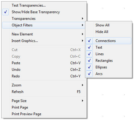
To adjust the transparency visibility, move the mouse pointer over a blank area of the Graphic canvas. Right-click and select Transparencies. The resulting sub-menu will list all of the available transparencies (or conditional statements) that currently exist in the component graphics.
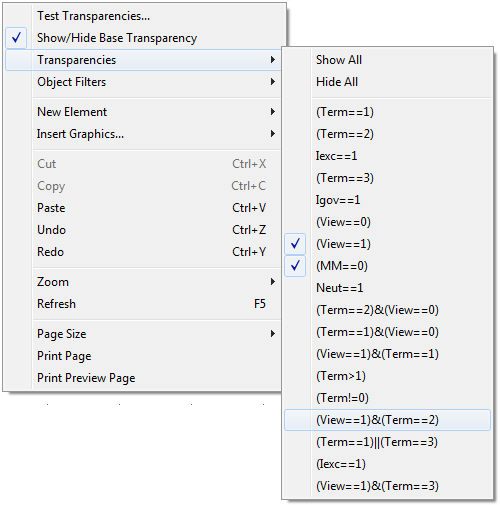
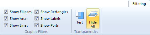
Simply select or de-select each transparency to make visible or invisible respectively. You can also select Show All or Hide All or, press the Show All/Hide All button on the Filtering tab of the ribbon control bar to toggle the visibility of all transparencies.:
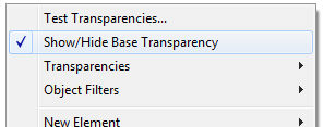
The base transparency contains any graphical objects and port connections that do not possess a defined conditional statement (i.e. are not part of a defined transparency). The base transparency may be toggled on and off using the pop-up menu: Move the mouse pointer over a blank area of the Graphic canvas. Right-click and select Show/Hide Base Transparency.
Instead of turning transparencies on and off through the right-click menu (which can become cumbersome as the number of transparencies increases), you can set and test the visible transparencies directly using the component parameter dialog.
Right-click on a blank part of the canvas and select Test Transparencies... from the pop-up menu. Or, press the Test button on the Filtering tab of the ribbon control bar:
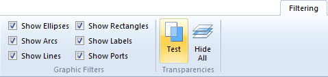
This feature provides a fully functional preview of the parameter dialogs as they would be seen by a user. Simply set all the choice lists to the desired settings and click the OK button – the graphical transparencies pertaining to that setting will become visible in the Graphic canvas.
In addition to graphical transparencies, you may also use Graphic Filters to help alleviate graphical clutter. Graphic filters allow the user to view objects based on the graphic object type (i.e. port connections, text labels, etc.).
To adjust graphic filters, the most straightforward method is to use the Graphic Filters section in the Filtering of the ribbon control bar.
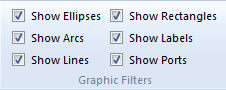
Another method is to use the right-click menu: Move the mouse pointer over a blank area of the Graphic canvas. Right-click and select Graphic Filters.