The thyristor is usually latched ON by a firing pulse supplied to the gate terminal, but is turned OFF according to voltage and current conditions across the device itself. An external control signal is required to generate the gate firing pulses.
The thyristor assumes a fixed small ON and a large OFF resistance. The thyristor state will change under the following conditions:
The forward bias voltage across the device is greater than or equal to the Forward Voltage Drop parameter input AND the gate signal goes from 0 to 1 (i.e. firing pulse is issued).
The forward bias voltage across the device is greater than or equal to the Forward Voltage Drop parameter input AND the gate signal is preset to 1 (i.e. firing angle = 0°). A turn ON under this situation is NOT interpolated (for an interpolated turn ON with firing angle = 0°, use the Diode).
The forward bias voltage across the device is greater than or equal to Forward Break-Over Voltage parameter input.
Turning OFF occurs with the device current reaching zero.
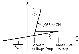
The V-I characteristic for the thyristor model is shown below:
The Interpolation Algorithm is automatically invoked during all naturally commutated turn ON and turn OFF events (including Forward Break-Over), to calculate the exact instant of switching. Please note however, that the user is provided a choice to interpolate the incoming gate signal.
The extinction time is also represented. The thyristor therefore, will re-fire following a turn OFF if the Minimum Extinction Time parameter input has not elapsed before the forward voltage rises above the Forward Voltage Drop parameter input. This will occur even in the absence of a turn on signal.
NOTE: Reverse recovery time (i.e. the time for which a finite reverse current flows in the device, following a turn OFF) of the diode is assumed zero. If the ON resistance is zero or smaller than the Switching Threshold value, the closed state will be modeled as an ideal short circuit.
![]()