The analysis of both overhead lines and underground cables begins with two well-known equations, sometimes referred to as the 'fundamental' or 'telegrapher's equations' [5], [7] and [24].
Consider a short transmission segment, whose length is small when compared to the wavelength, and the ground is the voltage reference. The system will possess a series-impedance and shunt-admittance, which is illustrated graphically as shown in Figure 8-5:

Figure 8-5 – Representation of a Relatively Small Transmission Line Segment
Given that Z and Y are the system impedance and admittance per unit length respectively, V is the conductor voltage and I is the conductor current, then the system in Figure 8-5 is described mathematically by the telegrapher’s equations (as the limit Dxg 0):
|
|
|
|
|
(8-3) |
In multi-conductor systems, Z and Y are square matrices, and V and I are vectors, both with dimension equal to the total equivalent number of conductors.
The derivation of Z and Y differs depending on the system. Specifically whether the system is underground or in air, or whether the conductors are bare (i.e. overhead lines) or bundled in cables.
Solving the Y and Z matrices for cable systems is a bit more involved than that of aerial transmission lines. In most practical systems, cables will possess multiple conducting layers, and most often run underground.
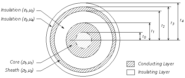
The LCP includes algorithms to solve single-core (SC) coaxial type cable systems: SC cables will consist of a centre conductor, and can include up to three concentric, conducting layers. Each conducting layer must be separated by an insulating layer, where the outermost insulating layer between the cable and earth is optional. The centre conductor can be either a hollow pipe possessing a finite thickness, or a solid, cylindrical conductor (by entering an inner radius r0 = 0.0). Any insulated conducting layer of each SC cable may be grounded mathematically, where the voltage along the full length of that conductor will be assumed to be 0.0.
A cross-section of an SC cable consisting of core and sheath conductors is illustrated in Figure 8-6.

Figure 8-6: Cross-Section of a 2-Conducting Layer SC Cable
Where,
|
|
Relative permeability |
|
|
Relative permittivity |
|
|
Resistivity [Wm] |
|
|
Radius of each layer [m] |
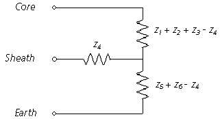
Apart from the centre conductor, each concentric conducting layer is represented by a combination of inner and outer surface impedances, as well as mutual impedance between it and the adjacent conductors. Each insulating layer is characterized by a single impedance with no mutual components. As such, and with respect to the series impedance, the SC cable shown in Figure 8-6 can be represented by the following equivalent circuit:

Figure 8-7: Cross-Section of a 2-Layer Coaxial Cable
NOTE: This method of circuit equivalency can be extended to consider any number of coaxial layers. The Line Constants Program extends this method to a maximum of 4 conducting layers plus 4 insulating layers.
This equivalent circuit can be derived by considering the effects of two circulating currents: The first flowing down the core conductor and returning back through the sheath, and the second down the sheath and back through the surrounding media [7].
The series impedance Z of n, single-core cables is given as follows:
|
|
(8-4) |
Where,
|
|
The SC cable internal impedance matrix |
|
|
The return media (earth) impedance matrix |
The elements of Zi and Z0 are themselves sub-matrices of dimension m x m, where m corresponds to the number of conducting layers in each respective cable n. If Equation 9-4 is rewritten in matrix format, it would appear as follows:
|
|
(8-5) |
Where,
|
|
Internal impedance sub-matrix of each respective SC cable |
|
|
Earth return impedance sub-matrix |
The SC cable representation in Figure 8-7 (i.e. m = 2) corresponds to an internal impedance sub-matrix given as follows:
|
|
(8-6) |
Where,
|
|
Core Self Impedance |
|
|
Mutual Impedance between Core and Sheath |
|
|
Sheath Self Impedance |
The earth return impedance sub-matrix in the case of Figure 8-7 is given as:
|
|
(8-7) |
Where,
|
|
Earth return mutual impedance between cables j and k. |
NOTE: For more information on the derivation of earth return impedance, see the section entitled Mutual Impedance with Earth Return in this chapter.
There is more than one method by which to calculate the individual internal impedances of an SC cable: One popular method is to solve them directly by using the well-known Bessel function based equations [3]. The LCP instead solves these quantities by way of equivalent analytical approximations as described in [7], which are generally much better suited for digital computation.
In an ideal sense, the Bessel function approach is of course more accurate, as these equations directly describe the theoretical characteristics of the conductor impedances. However when solved numerically in a digital program, the Bessel functions themselves can quickly become mired in precision overflow/underflow problems (In(x) tends to infinity and Kn(x) tends to zero), and additional steps must be taken avoid these situations. Also, algorithms available to solve these functions are themselves a combination of approximate formulae [14].
The Wedepohl/Wilcox approximations outlined in [7] are exact at very low and very high frequency. The error between these and the Bessel based equations for impedance of a solid cylinder, peaks at about 0.5% at mid-frequencies. The approximation error for the annulus impedances is even smaller, and approaches the exact functions with increasing accuracy as the thickness of the annulus becomes small compared with the radius of the annulus. The advantage to using these formulae over the Bessel function based impedances is mainly stability and speed of solution. The error introduced by the approximation equations is negligible in the time domain.
The equations for the individual impedances z1 to z6 in Figure 8-7 are given as follows. Both the Bessel function and equivalent approximate formula are presented for comparison:
Internal Impedance of Core Outer Surface (Solid Cylinder):
|
Approximate: |
|
(8-8) |
|
Bessel: |
|
Internal Impedance of Core Outer Surface (Annulus):
|
Approximate: |
|
(8-9) |
|
Bessel: |
|
Core Outer Insulator Impedance:
|
|
(8-10) |
Internal Impedance of Sheath Inner Surface:
|
Approximate: |
|
(8-11) |
|
Bessel: |
|
Sheath Mutual Impedance:
|
Approximate: |
|
(8-12) |
|
Bessel: |
|
Internal Impedance of Sheath Outer Surface:
|
Approximate: |
|
(8-13) |
|
Bessel: |
|
Outer Insulator Impedance:
|
|
(8-14) |
Where,
|
|
Modified Bessel function of the first kind |
|
|
Modified Bessel function of the second kind |
|
|
|
Deriving the shunt admittance matrix Y for a system of SC cables is relatively simple compared to complexities of the series impedance. Y is based on the potential coefficient matrix P:
|
|
(8-15) |
Where,
|
|
The SC cable internal potential coefficient matrix |
The elements of Pi are themselves sub-matrices of dimension m x m, where m corresponds to the number of conducting layers in each respective cable n. If Equation 8-15 is rewritten in matrix format, it would appear as follows:
|
|
(8-16) |
Where,
|
|
Internal potential coefficient sub-matrix of each cable |
The SC cable representation in Figure 8-6 (i.e. m = 2) corresponds to an internal impedance sub-matrix given as follows:
|
|
(8-17) |
Where,
|
|
Core Potential Coefficient |
|
|
Sheath Potential Coefficient |
The shunt admittance matrix Y is then:
|
|
(8-18) |
Note that in underground systems, the surrounding earth acts as an electrostatic shield resulting in null off-diagonal elements in Y [7].
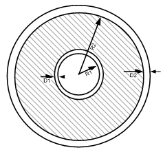
The inclusion of semi-conducting layers to the coaxial cable model is based on reference [29]. The semiconductor layers can be easily added by modifying the properties of the main insulation layer (ex. by changing the permittivity of the insulation).

Figure 8-8: Cross-Section of an Coaxial Cable with Semi-Conductor Layers
|
|
(8-19) |
Where,
|
|
Outer radius of the inner conductor |
|
|
Outer radius of the insulator |
|
|
Thickness of inner semiconducting screen |
|
|
Thickness of outer semiconducting screen |
|
|
|
|
|
|
|
|
|
Assumptions
See reference [30].
The capacitance of the semi-conducting layers is neglected. The permittivity of semi-conducting layers is very high compared to the insulator permittivity (e.g. typical values for relative permittivity of the semi-conducting layers and insulators are 1000 and 3 respectively), hence the capacitance of the semi-conducting layers is much higher than that of insulator. In the admittance equivalent circuit of the cable, two capacitors are in series. The total capacitance is
|
|
(8-20) |
Since ![]() , then
, then ![]() .
.
The conductivity of the semi-conducting layer is much lower than that of core or sheath; hence the relative contribution of the longitudinal current in the semi-conducting layers is negligible. Typical values for conductivity of the core and the semi-layers are 1e8 and 10 S/m. Note that the thickness of the first semiconducting layer must be less than the R2 - R1 and thickness of the second semiconducting layer must be less than the R3 - R2 , where R3 is the outer radius of the sheath.
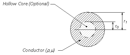
Deriving the series impedance Z and the shunt admittance Y for overhead lines is a relatively straightforward procedure in comparison to cables. This is mainly due to the fact that overhead conductors are generally simple –that is, each medium consists of a single, cylindrical conductor with no additional layers separated by insulation. The Line Constants Program provides the option to model an overhead conductor as both solid or hollow (i.e. as a conducting annulus).

Figure 8-9: Cross-Section of an Overhead Conductor
Where,
|
|
Relative permeability |
|
|
Resistivity [Wm] |
|
|
Radius [m] |
Each overhead conductor is modeled assuming a perfect cylindrical shape, which may possess a hollow core. As such, the conductor is represented by a combination of inner and outer surface impedances. If the conductor is solid, only the outer surface impedance is considered. The composition of the conductor is assumed to be homogeneous – that is, composite conductors, such as ACSR must be approximated as homogeneous.
The series impedance Z of n, overhead lines is given as follows:
|
|
(8-21) |
Where,
|
|
The internal impedance matrix |
|
|
The earth return impedance matrix |
NOTE: For more information on the derivation of earth return impedance, see the section entitled Mutual Impedance with Earth Return in this chapter
If Equation 8-21 is rewritten in matrix format, it would appear as follows:
|
|
(8-22) |
Where,
|
|
Internal impedance of each respective conductor |
|
|
Earth return impedance between conductors j and k |
The internal impedance for an overhead conductor is given as shown below. The LCP uses an analytical approximation to the well known Bessel based equations. Both the analytical approximation and Bessel equations are given here for easy reference:
NOTE: See the section entitled Underground Cables in this chapter for a detailed explanation why approximations are chosen over the Bessel method.
Internal Impedance of an Overhead Conductor (Solid Cylinder):
|
Approximate: |
|
(8-23) |
|
Bessel: |
|
Internal Impedance of an Overhead Conductor (Hollow Core):
|
Approximate: |
|
(8-24) |
|
Bessel: |
|
Where,
|
|
Modified Bessel function of the first kind |
|
|
Modified Bessel function of the second kind |
|
|
|
The shunt admittance matrix Y for aerial transmission systems can be easily derived, due to the fact that the surrounding air may be assumed as loss less, and the ground potential considered zero [24]. Therefore:
|
|
(8-25) |
Where,
|
|
Frequency [rad/s] |
|
|
Permittivity of free space |
|
|
Distances as described in the next section entitled Mutual Impedance with Earth Return [m]. |