The Frequency-Dependent (Phase) Model
Editing Model Component Parameters
There are two types of distributed (i.e. travelling wave) transmission models that may be selected to represent your transmission corridor: The Bergeron model and the Frequency-Dependent (Phase) model. These models exist as components in the master library and each include adjustable properties. The requirements for your study will determine which of the models is suitable.
The Bergeron model represents the L and C elements of a p-section in a distributed manner (not using lumped parameters like p-sections). It is accurate only at the specified frequency and is suitable for studies where the specified frequency load-flow is most important (e.g. relay studies).
When using the Bergeron model, it is not always necessary to use a tower component to represent a transmission line. If you are modeling a three-phase system, then you can enter the line data, in admittance or impedance format, directly by substituting the Manual Entry of Y, Z component.

This component can be added just as you were adding a tower component. Keep in mind that this component substitutes for the tower component, and you still need the Bergeron model present in your transmission line configuration.
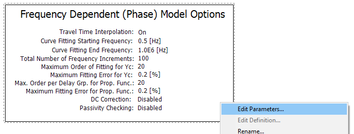
The Frequency-Dependent (Phase) model represents the frequency dependence of all parameters by direct formulation in the phase domain. It is therefore accurate for all transmission configurations, including unbalanced line geometries.
This model should always be the model of choice, unless another model is chosen for a specific reason. This model is the most advanced and accurate time domain line model in the world!
NOTE: For further technical details, or more information on choosing a line model, see the Transmission Lines and Cables topic in the EMTDC section.
Model components can be added to the editor in a couple different ways. The easiest and most straightforward way is to use the ribbon control bar. Simply select one of the available models and place it on the Schematic canvas. See Adding Components to a Project for more details.

Another way is to use the context menu. On the Schematic tab, move the mouse pointer over a blank area of the window. Right-click and select Choose Model. A sub-menu will appear containing a list of all model components available in the master library. Select a model and it will automatically be added.

You can also copy and paste model components directly from any library project. Open the library in Schematic view and select a line model component, right-click on the component and select Copy (or press Ctrl + c). Open the Editor section (tab), right-click over a blank area and select Paste (or press Ctrl + v).
Model component parameters may be edited through the corresponding parameters dialog window. Right-click over the model component (without selecting it) and select Edit Parameters... to access this dialog.