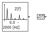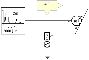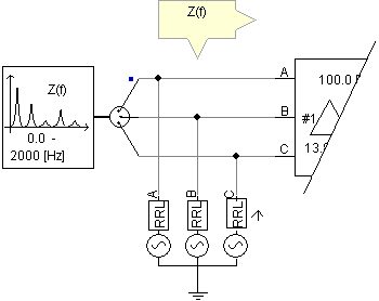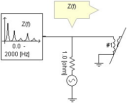

This component is used to find the multi-port impedance of any electric network over a defined frequency range. The output data (in the form of a text file) can then be analyzed in an external graphical analysis program. This component may be connected directly to either a 1-phase or 3-phase network as follows:


3-Phase Connections

1-Phase Connection
The Interface to Harmonic Impedance Solution generates the system impedance matrix for any electric network in the phase domain. Then the matrix is collapsed into an equivalent matrix as seen from the interface point. This is repeated for each frequency as specified in the component parameter inputs.
In instances where transmission line and cable models are present, this component uses RLC data directly, avoiding integration and/or curve fitting errors. The equations are solved in the phase domain itself without using sequence networks, thus giving accurate representations for unbalanced transmission lines, Y-D transformers etc.
This component extracts the status of breakers/faults and variable RLC values in the first time step and the solution is found in the second time step. Therefore, the user need only run the simulation for 2 time steps.
The following assumptions are made in the Harmonic Impedance Solution:
Transformer saturation and arresters are assumed to be in their unsaturated region.
All the power electronic devices are assumed to be in their OFF state.
Synchronous and Induction Machines are represented as a grounded inductor.
The 0-sequence impedance of an SVC is represented as the primary-delta leakage reactance of the transformer, and the +/- sequence impedance is represented by the defined shunt loss conductance.
The minimum frequency to calculate system impedance is 1 mHz. Therefore, DC resistance is not computed.
NOTE: User written components interfaced to EMTDC via the Node Based (GGIN) Electric Interface, may not be taken into account in the Harmonic Impedance Solution. Custom components interfaced via the Equivalent Conductance (GEQ) Electric Interface, which includes the Variable RLC component, will always be included however.
More: |
Main ConfigurationMain Configuration
Name for Identification |
Text |
Optional text parameter for identification of the component. |
||
Min Frequency |
|
REAL |
Literal |
Enter the minimum frequency for Harmonic Impedance Solution range [Hz] |
|
|
|
|
|
Max Frequency |
|
REAL |
Literal |
Enter the maximum frequency for Harmonic Impedance Solution range [Hz] |
|
|
|
|
|
Frequency Increment Type |
|
Choice |
|
Select Linear Scale or Log Scale |
|
|
|
|
|
Freq Increment |
|
REAL |
Literal |
[Hz] |
|
|
|
|
|
# of Frequencies |
|
INTEGER |
Literal |
|
|
|
|
|
|
Output Filename |
|
Text |
|
Enter a name for the output file to be created |
|
|
|
|
|
Impedance Output Type |
|
Choice |
|
Select +ve, -ve and 0 Sequence Impedances or Phase Impedances |
|
|
|
|
|
Frequency Output Units |
|
Choice |
|
Select Hz, Radians/Sec, LOG10(Hz) or LOG10(Radians/Sec) |
|
|
|
|
|
Impedance Output Units |
|
Choice |
|
Select Magnitude and Phase (Deg) or Real, Imaginary (ohms) |
|
|
|
|
|
View |
|
Choice |
|
Select the desired graphical display: Default or Compact. |