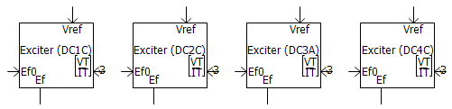
This component models a set of IEEE Standard 421.5-2016 DC exciter models. Models included are DC1C, DC2C, DC3A and DC4C. According to the standard, DC1A, DC2A and DC4B, introduced in the older revisions of the standard, may be replaced with the newer models (with appropriate new parameter selection, which are included in the new component).
The models provide a continuous DC current for the field winding of a synchronous machine using closed-loop control. The main theories behind this model are introduced in IEEE Std 421.5-2016.
The main objectives of an excitation system based on its application are as follows:
Constant terminal voltage: Helps a synchronous generator to maintain its terminal voltage at the desired level.
Constant power factor: Helps a synchronous motor to maintain its power factor at the desired level.
Inputs:
Ef0: Input for the corresponding synchronous machine output field voltage signal during the initialization period in per-unit [pu].
[VT/IT]: Input for the synchronous machine output RMS terminal voltage, real terminal current and imaginary terminal current, in 3-element signal array format.
Vref: Input for the desired reference voltage for the synchronous machine terminal in per-unit [pu].
VS: Input for the output signal generated by the corresponding power system stabilizer in per-unit [pu].
This input is provided only when using the exciter with a power system stabilizer. Please note that no VS input is available for exciter DC3A.
Outputs:
Ef: Outputs the calculated field voltage signal in per-unit, to be applied directly to the corresponding synchronous machine [pu].
Vref0: Outputs the initialized value of the reference voltage (Vref) in per-unit [pu]. This port is visible only if the parameter Output Internally Computed Initial Vref? is selected as Yes.
More: |
DC Exciter Transfer Functions (2016) |
Name |
Text |
Optional text parameter for identification of the component. |
||
DC Exciter Type |
|
Choice |
|
Select DC1A, DC2A, DC3A or DC4A as described in DC Exciter Transfer Functions (2016). |
|
|
|
|
|
Exciter Status => 0-Initialize;1-Normal |
|
INTEGER |
Variable |
Identifies the exciter status: 0-Initilized or 1-Normal.
This variable can come from Output Variables for Controller Initialization section of the corresponding synchronous machine parameter. |
|
|
|
|
|
Output Internally Computed Initial Vref? |
|
Choice |
|
Select Yes or No |
|
|
|
|
|
Load Compensating Resistance (Rc) |
|
REAL |
Constant |
[pu]. See Load Compensation for more details. |
|
|
|
|
|
Load Compensating Reactance (Xc) |
|
REAL |
Constant |
[pu]. See Load Compensation for more details. |
|
|
|
|
|
Transducer Time Constant (Tr) |
|
REAL |
Constant |
[s]. See Load Compensation for more details. |
DC1C: Regulator ConstantsDC1C: Regulator Constants
NOTE: See DC Exciter Transfer Functions for more details.
Is There a Stabilizer? |
|
Choice |
|
Select Yes or No.
Selecting Yes will add a port to the component graphic to input the signal VS. |
|
|
|
|
|
Under Excitation Limit Input Signal? |
|
Choice |
|
Select None, Summation point or Take-over.
Selecting Summation point or Take-over will enable the Under Excitation Limiter Input (VUEL) parameter. |
|
|
|
|
|
Over Excitation Limit Input Signal? |
|
Choice |
|
Select None, Summation point or Take-over.
Selecting Summation point or Take-over will enable the Over Excitation Limiter Input (VOEL) parameter. |
|
|
|
|
|
Under Excitation Stator Current Limiter Input Signal? |
|
Choice |
|
Select None, Summation point or Take-over.
Selecting Summation point or Take-over will enable the Under Excitation Stator Current Limiter Input (VSCLu) parameter. |
|
|
|
|
|
Over Excitation Stator Current Limiter Input Signal? |
|
Choice |
|
Select None, Summation point N/A or Take-over.
Selecting Summation point or Take-over will enable the Over Excitation Stator Current Limiter Input (VSCLo) parameter. |
|
|
|
|
|
Lead Time Constant (TC) |
|
REAL |
Constant |
[s]. |
|
|
|
|
|
Lag Time Constant (TB) |
|
REAL |
Constant |
[s]. |
|
|
|
|
|
Regulator Gain (KA) |
|
REAL |
Constant |
[pu]. |
|
|
|
|
|
Regulator Time Constant (TA) |
|
REAL |
Constant |
[s]. |
|
|
|
|
|
Maximum Regulator Output (VRMAX) |
|
REAL |
Constant |
[pu]. |
|
|
|
|
|
Minimum Regulator Output (VRMIN) |
|
REAL |
Constant |
[pu]. |
DC1C: Exciter ParametersDC1C: Exciter Parameters
NOTE: See DC Exciter Transfer Functions for more details.
Exciter Time Constant (TE) |
|
REAL |
Constant |
[s]. |
|
|
|
|
|
Exciter Field Voltage Lower Limit (EFDmin) |
|
REAL |
Constant |
[pu]. |
|
|
|
|
|
Excitation Type? |
|
Choice |
|
Select Self or Separately.
Selecting separately will disregard EFD feedback impact on VR. |
|
|
|
|
|
Saturation at Efd1 (SE(Efd1)) |
|
REAL |
Constant |
[pu]. |
|
|
|
|
|
Exciter Voltage for SE1 (Efd1) |
|
REAL |
Constant |
[pu]. |
|
|
|
|
|
Saturation at Efd2 (SE(Efd2)) |
|
REAL |
Constant |
[pu]. |
|
|
|
|
|
Exciter Voltage for SE2 (Efd2) |
|
REAL |
Constant |
[pu]. |
|
|
|
|
|
Under Excitation Limiter Input (VUEL) |
|
REAL |
Variable |
[pu]. |
|
|
|
|
|
Over Excitation Limiter Input (VOEL) |
|
REAL |
Variable |
[pu]. |
|
|
|
|
|
Under Excitation Stator Current Limiter Input (VSCLu) |
|
REAL |
Variable |
[pu]. |
|
|
|
|
|
Over Excitation Stator Current Limiter Input (VSCLo) |
|
REAL |
Variable |
[pu]. |
DC1C: Rate Feedback ParametersDC1C: Rate Feedback Parameters
NOTE: See DC Exciter Transfer Functions for more details.
Rate Feedback Gain (KF) |
|
REAL |
Constant |
[pu]. |
|
|
|
|
|
Rate Feedback Time Constant (TF) |
|
REAL |
Constant |
[s]. |
DC2C: Regulator ConstantsDC2C: Regulator Constants
NOTE: See DC Exciter Transfer Functions for more details.
Is There a Stabilizer? |
|
Choice |
|
Select Yes or No.
Selecting Yes will add a port to the component graphic to input the signal VS. |
|
|
|
|
|
Under Excitation Limit Input Signal? |
|
Choice |
|
Select None, Summation point or Take-over.
Selecting Summation point or Take-over will enable the Under Excitation Limiter Input (VUEL) parameter. |
|
|
|
|
|
Over Excitation Limit Input Signal? |
|
Choice |
|
Select None, Summation point or Take-over.
Selecting Summation point or Take-over will enable the Over Excitation Limiter Input (VOEL) parameter. |
|
|
|
|
|
Under Excitation Stator Current Limiter Input Signal? |
|
Choice |
|
Select None, Summation point or Take-over.
Selecting Summation point or Take-over will enable the Under Excitation Stator Current Limiter Input (VSCLu) parameter. |
|
|
|
|
|
Over Excitation Stator Current Limiter Input Signal? |
|
Choice |
|
Select None, Summation point N/A or Take-over.
Selecting Summation point or Take-over will enable the Over Excitation Stator Current Limiter Input (VSCLo) parameter. |
|
|
|
|
|
Lead Time Constant (TC) |
|
REAL |
Constant |
[s]. |
|
|
|
|
|
Lag Time Constant (TB) |
|
REAL |
Constant |
[s]. |
|
|
|
|
|
Regulator Gain (KA) |
|
REAL |
Constant |
[pu]. |
|
|
|
|
|
Regulator Time Constant (TA) |
|
REAL |
Constant |
[s]. |
|
|
|
|
|
Maximum Regulator Output (VRMAX) |
|
REAL |
Constant |
[pu]. |
|
|
|
|
|
Minimum Regulator Output (VRMIN) |
|
REAL |
Constant |
[pu]. |
DC2C: Exciter ParametersDC2C: Exciter Parameters
NOTE: See DC Exciter Transfer Functions for more details.
Exciter Time Constant (TE) |
|
REAL |
Constant |
[s]. |
|
|
|
|
|
Exciter Field Voltage Lower Limit (EFDmin) |
|
REAL |
Constant |
[pu]. |
|
|
|
|
|
Excitation Type? |
|
Choice |
|
Select Self or Separately.
Selecting separately will disregard EFD feedback impact on VR. |
|
|
|
|
|
Saturation at Efd1 (SE(Efd1)) |
|
REAL |
Constant |
[pu]. |
|
|
|
|
|
Exciter Voltage for SE1 (Efd1) |
|
REAL |
Constant |
[pu]. |
|
|
|
|
|
Saturation at Efd2 (SE(Efd2)) |
|
REAL |
Constant |
[pu]. |
|
|
|
|
|
Exciter Voltage for SE2 (Efd2) |
|
REAL |
Constant |
[pu]. |
|
|
|
|
|
Under Excitation Limiter Input (VUEL) |
|
REAL |
Variable |
[pu]. |
|
|
|
|
|
Over Excitation Limiter Input (VOEL) |
|
REAL |
Variable |
[pu]. |
|
|
|
|
|
Under Excitation Stator Current Limiter Input (VSCLu) |
|
REAL |
Variable |
[pu]. |
|
|
|
|
|
Over Excitation Stator Current Limiter Input (VSCLo) |
|
REAL |
Variable |
[pu]. |
DC2C: Rate Feedback ParametersDC2C: Rate Feedback Parameters
NOTE: See DC Exciter Transfer Functions for more details.
Rate Feedback Gain (KF) |
|
REAL |
Constant |
[pu]. |
|
|
|
|
|
Rate Feedback Time Constant (TF) |
|
REAL |
Constant |
[s]. |
DC3A: Regulator ParametersDC3A: Regulator Parameters
NOTE: See DC Exciter Transfer Functions for more details.
Rheostat Travel Time (TRH) |
|
REAL |
Constant |
[s]. |
|
|
|
|
|
Maximum Regulator Output (VRMAX) |
|
REAL |
Constant |
[pu]. |
|
|
|
|
|
Minimum Regulator Output (VRMIN) |
|
REAL |
Constant |
[pu]. |
|
|
|
|
|
Fast Raise/Lower setting (Kv) |
|
REAL |
Constant |
[pu]. |
DC3A: Exciter ParametersDC3A: Exciter Parameters
NOTE: See DC Exciter Transfer Functions for more details.
Exciter Time Constant (TE) |
|
REAL |
Constant |
[s]. |
|
|
|
|
|
Excitation Type? |
|
Choice |
|
Select Self or Separately.
Selecting separately will disregard EFD feedback impact on VR. |
|
|
|
|
|
Saturation at Efd1 (SE(Efd1)) |
|
REAL |
Constant |
[pu]. |
|
|
|
|
|
Exciter Voltage for SE1 (Efd1) |
|
REAL |
Constant |
[pu]. |
|
|
|
|
|
Saturation at Efd2 (SE(Efd2)) |
|
REAL |
Constant |
[pu]. |
|
|
|
|
|
Exciter Voltage for SE2 (Efd2) |
|
REAL |
Constant |
[pu]. |
DC4C: Regulator ConstantsDC4C: Regulator Constants
NOTE: See DC Exciter Transfer Functions for more details.
Is There a Stabilizer? |
|
Choice |
|
Select Yes or No.
Selecting Yes will add a port to the component graphic to input the signal VS. |
|
|
|
|
|
Under Excitation Limit Input Signal? |
|
Choice |
|
Select None, Summation point or Take-over.
Selecting Summation point or Take-over will enable the Under Excitation Limiter Input (VUEL) parameter. |
|
|
|
|
|
Over Excitation Limit Input Signal? |
|
Choice |
|
Select None, Summation point or Take-over.
Selecting Summation point or Take-over will enable the Over Excitation Limiter Input (VOEL) parameter. |
|
|
|
|
|
Under Excitation Stator Current Limiter Input Signal? |
|
Choice |
|
Select None, Summation point or Take-over.
Selecting Summation point or Take-over will enable the Under Excitation Stator Current Limiter Input (VSCLu) parameter. |
|
|
|
|
|
Over Excitation Stator Current Limiter Input Signal? |
|
Choice |
|
Select None, Summation point N/A or Take-over.
Selecting Summation point or Take-over will enable the Over Excitation Stator Current Limiter Input (VSCLo) parameter. |
|
|
|
|
|
Regulator Proportional Gain (KPR) |
|
REAL |
Constant |
[pu]. |
|
|
|
|
|
Regulator Integral Gain (KIR) |
|
REAL |
Constant |
[pu]. |
|
|
|
|
|
Regulator Derivative Gain (KDR) |
|
REAL |
Constant |
[pu]. |
|
|
|
|
|
Regulator Derivative Filter Time Constant (KIR) |
|
REAL |
Constant |
[s]. |
|
|
|
|
|
Regulator Gain (KA) |
|
REAL |
Constant |
[pu]. |
|
|
|
|
|
Regulator Time Constant (TA) |
|
REAL |
Constant |
[s]. |
|
|
|
|
|
Maximum Regulator Output (VRMAX) |
|
REAL |
Constant |
[pu]. |
|
|
|
|
|
Minimum Regulator Output (VRMIN) |
|
REAL |
Constant |
[pu]. |
DC4C: Exciter ParametersDC4C: Exciter Parameters
NOTE: See DC Exciter Transfer Functions for more details.
Exciter Time Constant (TE) |
|
REAL |
Constant |
[s]. |
|
|
|
|
|
Exciter Field Proportional Constant (KEc) |
|
REAL |
Constant |
[pu]. |
|
|
|
|
|
Exciter Minimum Output Voltage (VEMIN) |
|
REAL |
Constant |
[pu]. |
|
|
|
|
|
Excitation Type? |
|
Choice |
|
Select Self or Separately.
Selecting separately will disregard EFD feedback impact on VR. |
|
|
|
|
|
Saturation at Efd1 (SE(Efd1)) |
|
REAL |
Constant |
[pu]. |
|
|
|
|
|
Exciter Voltage for SE1 (Efd1) |
|
REAL |
Constant |
[pu]. |
|
|
|
|
|
Saturation at Efd2 (SE(Efd2)) |
|
REAL |
Constant |
[pu]. |
|
|
|
|
|
Exciter Voltage for SE2 (Efd2) |
|
REAL |
Constant |
[pu]. |
|
|
|
|
|
Under Excitation Limiter Input (VUEL) |
|
REAL |
Variable |
[pu]. |
|
|
|
|
|
Over Excitation Limiter Input (VOEL) |
|
REAL |
Variable |
[pu]. |
|
|
|
|
|
Under Excitation Stator Current Limiter Input (VSCLu) |
|
REAL |
Variable |
[pu]. |
|
|
|
|
|
Over Excitation Stator Current Limiter Input (VSCLo) |
|
REAL |
Variable |
[pu]. |
DC4C: Rate Feedback ParametersDC4C: Rate Feedback Parameters
NOTE: See DC Exciter Transfer Functions for more details.
Rate Feedback Gain (KF) |
|
REAL |
Constant |
[pu]. |
|
|
|
|
|
Rate Feedback Time Constant (TF) |
|
REAL |
Constant |
[s]. |
DC4C: Potential Circuit ParametersDC4C: Potential Circuit Parameters
NOTE: See DC Exciter Transfer Functions for more details.
Potential Circuit Gain Coefficient (KP) |
|
REAL |
Constant |
[pu]. |
|
|
|
|
|
Potential Circuit Phase Angle (ThetaP) |
|
REAL |
Constant |
[deg]. |
|
|
|
|
|
Potential Circuit (Current) Gain Coefficient (KI) |
|
REAL |
Constant |
[pu]. |
|
|
|
|
|
Proportional Source Reactance (XL) |
|
REAL |
Constant |
[pu]. |
|
|
|
|
|
Rectifier Loading Factor (KC1) |
|
REAL |
Constant |
[pu]. |
|
|
|
|
|
Maximum Available Exciter Field Voltage (VBmax) |
|
REAL |
Constant |
[pu]. |
|
|
|
|
|
Logic Switch (SW1) |
|
Choice |
|
Select positions A or B. |