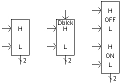
This component returns the firing pulse and the Interpolated Time Tag required for an interpolated turn-ON (or turn-OFF) of thyristors, IGBTs and GTOs, in the form of a two-element array. The first output element is a 0 or 1 and represents the actual gate control pulse. The second is information regarding the interpolated switching time.
The output is based on a comparison of high (H) and low (L) input signals. The low L input is normally a firing angle (a) order and the high H input is from a phase-locked oscillator or equivalent. The Interpolated Firing Pulses component can be set to produce timed firing pulses for:
A single GTO/IGBT
A 6-Pulse GTO/IGBT bridge
A single thyristor
NOTE: If a GTO or IGBT is used, then an input signal comparison is provided for the OFF signal as well.
More: |
Name for Identification |
Text |
Optional text parameter for identification of the component. |
||
Thyristor or GTO? |
|
Choice |
|
Select Thyristor or GTO (IGBT).
This parameter determines the format of the output control signal depending on whether the device being controlled is built with thyristors or GTOs. |
|
|
|
|
|
Number of Pulses |
|
Choice |
|
Select One or Six.
Select One if a single thyristor or GTO is to be controlled. Select six to provide output for a six-pulse, thyristor or GTO bridge. |
|
|
|
|
|
Add Block/Deblock Signal? |
|
Choice |
|
Select Yes or No.
If Yes is selected, the component will expect an additional external signal for blocking control, where:
|
|
|
|
|
|
Format of Pulse, Time Output: |
|
Choice |
|
Select To Individual Devices (6 outputs of dimension 2) or To Six Pulse Thyristor Group (2 outputs of dimension 6).
Select the first option to supply a custom built 6-pulse bridge with control signals. Select the latter option if controlling the 6-Pulse Bridge component. Note that this option is only enabled if Thyristor or GTO? | Thyristor and Number of Pulses | Six is selected. See Setting Up Firing Control. |
|
|
|
|
|
Band Limit Proximity Correction |
|
Choice |
|
Select Disarmed or Armed (must indicate H input band limits). See Setting Up Firing Control. |
Band Limit Proximity DataBand Limit Proximity Data
NOTE: These options are only enabled if Band Limit Proximity Correction | Armed is selected. See Setting Up Firing Control.
H Input Maximum Limit |
|
REAL |
Variable |
Enter the input upper band limit. |
|
|
|
|
|
H Input Minimum Limit |
|
REAL |
Variable |
Enter the input lower band limit. |
Block/Deblock Input |
|
Choice |
|
Select Group or Individual. That is, block the 6-pulse bridge as a group or individually (6 element external signal array). This is enabled only when Number of Pulses | Six is selected [s] |
Pulse Duration |
|
REAL |
Variable |
Output pulse duration. This is enabled only when Thyristor or GTO? | Thyristor is selected [s] |