
Single Thyristor Device
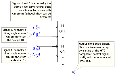
Single GTO Device
Band Limit Proximity Correction
The Interpolated Firing Pulses component may appear complicated at first, but it is actually quite simple and made to make life easier when setting up firing control. The following section describe some of the features of the Interpolated Firing Pulses component in a bit more detail.
There are a few types of output format configurations available in this component. This depends on the type of device being controlled (i.e. individual or six Thyristors, GTO/IGBTs or the 6-Pulse Bridge component). The following illustrates set-ups for most configurations:
|
|
|
|
Single Thyristor Device |
Single GTO Device |
|
|
|
|
Six Individual Thyristor Devices |
Six Individual GTO Devices |
|
|
|
6-Pulse Bridge Device |
One type of problem in the simulation of control signals for power electronic circuits is that of control signal logic failure. Logic failure can arise in any number of different circumstances, but one circumstance in particular is the misrepresentation of signal discontinuities due to finite time step increments. Without some form of error correction, discontinuous signals (ex. signals with piecewise linear segments) are impossible to perfectly replicate numerically in a computer program, unless of course the time step grid overlays exactly on all discontinuous points.

Failure Zone when in Proximity to Band Limits
Anyone familiar with simulating comparison type control systems (such as PWM) will recognize that, when performing comparisons of two signals, care must be exercised to prevent signal failure at the signal extremities. For example, consider the case when comparing a 0 to 360° sawtooth waveform with a firing angle signal in order to create a thyristor gate control. Depending on the time step Dt, the frequency f and the amplitude A of the sawtooth, there is a ’r;failure zone’ created.
By utilizing a linear interpolation algorithm specifically designed for this situation (ie. Band Limit Proximity Correction | Armed), the problem can be rectified. This will effectively remove the failure zones, as well as the rigid dependence on time step. Of course, time step is still a factor here, but its effects will be lessened considerably.

Interpolation Used Avoid PWM Logic Failure
Since the slope of both the PWM Carrier Signal (mPWM) and the Firing Angle Signal (mfa) are both known, the exact time at which the discontinuity should occur (zx) can be calculated. Once this quantity is known, then the Interpolated Time Tag (dx) can be calculated (as shown above for proximity to lower band limit). This in turn ensures that: 1) the situation is detected and 2) the exact time a switch should have occurred is known.
Related Topics